EasyManua.ls Logo

Sony TC-730 - 3-2. Electrical Adjustments

Sony TC-730
75 pages
Print Icon
To Next Page IconTo Next Page
To Previous Page IconTo Previous Page
Loading...
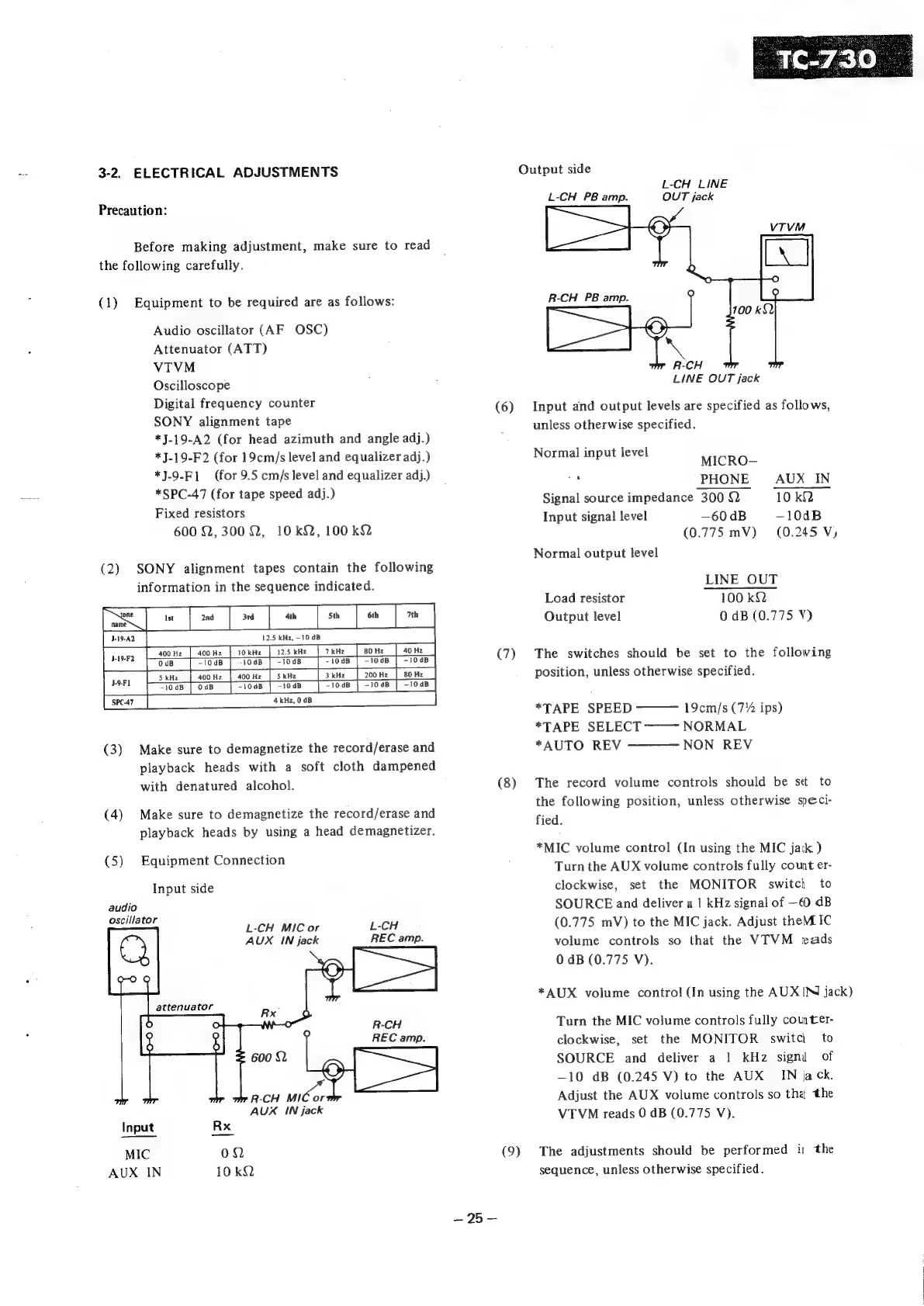
3-2,
ELECTRICAL
ADJUSTMENTS
Precaution:
Before
making
adjustment,
make
sure
to
read
the
following
carefully.
(1)
Equipment
to
be
required
are
as
follows:
Audio
oscillator
(AF
OSC)
Attenuator
(ATT)
VTVM
Oscilloscope
Digital
frequency
counter
SONY
alignment
tape
*J-19-A2
(for
head
azimuth
and
angle
adj.)
*J-19-F2
(for
19cm/s
level
and
equalizer
adj.)
*J-9-F]
(for
9.5
cm/s
level
and
equalizer
adj.)
*SPC-47
(for
tape
speed
adj.)
Fixed
resistors
600
2,3002,
10kQ,
100
k2
(2)
SONY
alignment
tapes
contain
the
following
information
in
the
sequence
indicated.
J-19-F2
12.5
kHz,
-10
dB
[soone
|
soone
|
ronnie
|
i2sene
|
7eH2_|
[a
[som
[som
|
[tous
[tod
[Tose
[=
tous
|
roe
|
1008
|
[ean
oo
|
ao
ne
|
[soon
|
sone
|
[twas
[ods
[1008
|
-1048
|
-1oas
|
10s
|
“1048
|
|
seca7
|
4
kHz,
0
dB
(3)
Make
sure
to
demagnetize
the
record/erase
and
playback
heads
with
a
soft
cloth
dampened
with
denatured
alcohol.
(4)
Make
sure
to
demagnetize
the
record/erase
and
playback
heads
by
using
a
head
demagnetizer.
(5)
Equipment
Connection
Input
side
audio
Hate
——
L-CH
MIC
or
L-CH
AUX
IN
jack
REC
amp.
REC
amp.
R-CH
ieee
AUX
IN
jack
Input
Rx
MIC
02
AUX
IN
10kQ
—-25—-—
(6)
(7)
(8)
(9)
Output
side
L-CH
LINE
L-CH
PB
amp.
OUT
jack
R-CH
PB
amp.
LINE
OUT
jack
Input
and
output
levels
are
specified
as
follows,
unless
otherwise
specified.
Normal
input
level
MICRO—
7s
PHONE
AUX
IN
Signal
source
impedance
300
Q
10
kQ
Input
signal
level
—60
dB
—10dB
(0.775
mV)
(0.245
Vy
Normal
output
level
LINE
OUT
Load
resistor
100
kQ
Output
level
0
dB
(0.775
VY)
The
switches
should
be
set
to
the
following
position,
unless
otherwise
specified.
*TAPE
SPEED
19cm/s
(7%
ips)
*TAPE
SELECT
——~
NORMAL
*AUTO
REV
—————
NON
REV
The
record
volume
controls
should
be
se
to
the
following
position,
unless
otherwise
speci-
fied.
*MIC
volume
control
(In
using
the
MIC
jack
)
Turn
the
AUX
volume
controls
fully
count
er-
clockwise,
set
the
MONITOR
switch
to
SOURCE
and
deliver
a
1
kHz
signal
of
—€0
dB
(0.775
mV)
to
the
MIC
jack.
Adjust
them.
IC
volume
controls
so
that
the
VTVM
reads
0
dB
(0.775
V).
*AUX
volume
control
(In
using
the
AUX
IN
jack)
Turn
the
MIC
volume
controls
fully
comter-
clockwise,
set
the
MONITOR
switci_
to
SOURCE
and
deliver
a
1
kHz
signi
of
—10
dB
(0.245
V)
to
the
AUX
IN
jack.
Adjust
the
AUX
volume
controls
so
tha
the
VTVM
reads
0
dB
(0.775
V).
the
The
adjustments
should
be
performed
i
sequence,
unless
otherwise
specified.