EasyManua.ls Logo

Sony TC-730 - Page 35

Sony TC-730
75 pages
Print Icon
To Next Page IconTo Next Page
To Previous Page IconTo Previous Page
Loading...
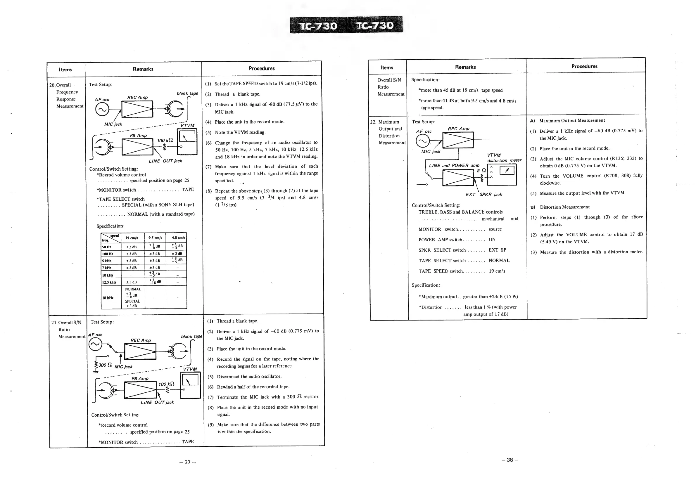
20.
Overall
Frequency
Test
Setup:
(1)
Set
the
TAPE
SPEED
switch
to
19
cm/s
(7-1/2
ips).
blank
tape
Thread
a
blank
tape.
Response
AF
osc
REC
Amp
P
Measurement
(3)
Deliver
a
1
kHz
signal
of
-80
dB
(77.5
LV)
to
the
—_
MIC
jack.
Place
the
unit
in
the
record
mode.
MIC
jack
oe
TV
TVM
(5)
Note
the
VT
VM
reading.
(6)
Change
the
frequecny
of
an
audio
oscillator
to
50
Hz,
100
Hz,
5
kHz,
7
kHz,
10
kHz,
12.5
kHz
and
18
kHz
in
order
and
note
the
VT
VM
reading.
LINE
OUT
jack
(7)
Make
sure
that
the
level
deviation
of
each
frequency
against
1
kHz
signal
is
within
the
range
Control/Switch
Setting:
*Recrod
volume
control
setnaiat
Syece,
doe
specified
position
on
page
25
*MONITOR
switch
.............---
*TAPE
SELECT
switch
See
take
Beals
SPECIAL
(with
a
SONY
SLH
tape)
specified.
Repeat
the
above
steps
(3)
through
(7)
at
the
tape
speed
of
9.5
cm/s
(3
3/4
ips)
and
4.8
cm/s
(1
7/8
ips).
bare
wi
Epens
NORMAL
(with
a
standard
tape)
+2
4B
SPECIAL
blank
tape
21.
Overall
S/N
Ratio
Measurement
|A&
Test
Setup:
Thread
a
blank
tape.
(2)
Deliver
a
1
kHz
signal
of
—60
dB
(0.775
mV)
to
the
MIC
jack.
osc
Place
the
unit
in
the
record
mode.
Record
the
signal
on
the
tape,
noting
where
the
recording
begins
for
a
later
reference.
ages
Disconnect
the
audio
oscillator.
Rewind
a
half
of
the
recorded
tape.
Terminate
the
MIC
jack
with
a
300
{2
resistor.
LINE
OUT
jack
(8)
Place
the
unit
in
the
record
mode
with
no
input
Control/Switch
Setting:
signal.
*Record
volume
control
Breage
bhi
bok
specified
position
on
page
25
(9)
Make
sure
that
the
difference
between
two
parts
is
within
the
specification.
*MONITOR
switch
..........-.-++--
=37
4
*more
than
45
dB
at
19
cm/s
tape
speed
LINE
and
POWER
amp
EXT
SPKR
jack
Control/Switch
Setting:
TREBLE,
BASS
and
BALANCE
controls
mechanical
MONITOR
switch.
POWER
AMP
switch
SPKR
SELECT
switch
TAPE
SELECT
switch
NORMAL
TAPE
SPEED
switch
19
cm/s
*more
than
41
dB
at
both
9.5
cm/s
and
4.8
cm/s
VT
VM
distortion
meter
mid
*Maximum
output.
.
greater
than
+23dB
(15
W)
less
than
1
%
(with
power
amp
output
of
17
dB)
—
38
—
Procedures
;
Maximum
Output
Measurement
Deliver
a
1
kHz
signal
of
—60
dB
(0.775
mV)
to
Place
the
unit
in
the
record
mode.
Adjust
the
MIC
volume
control
(R135,
235)
to
obtain
0
dB
(0.775
V)
on
the
VITVM.
Turn
the
VOLUME
control
(R708,
808)
fully
Measure
the
output
level
with
the
VT
VM.
Distortion
Measurement
Perform
steps
(1)
through
(3)
of
the
above
Adjust
the
VOLUME
control
to
obtain
17
dB
(5.49
V)
on
the
VITVM.
Measure
the
distortion
with
a
distortion
meter.