EasyManua.ls Logo

Sony TRINITRON KV-21V5A - Page 33

Sony TRINITRON KV-21V5A
62 pages
Print Icon
To Next Page IconTo Next Page
To Previous Page IconTo Previous Page
Loading...
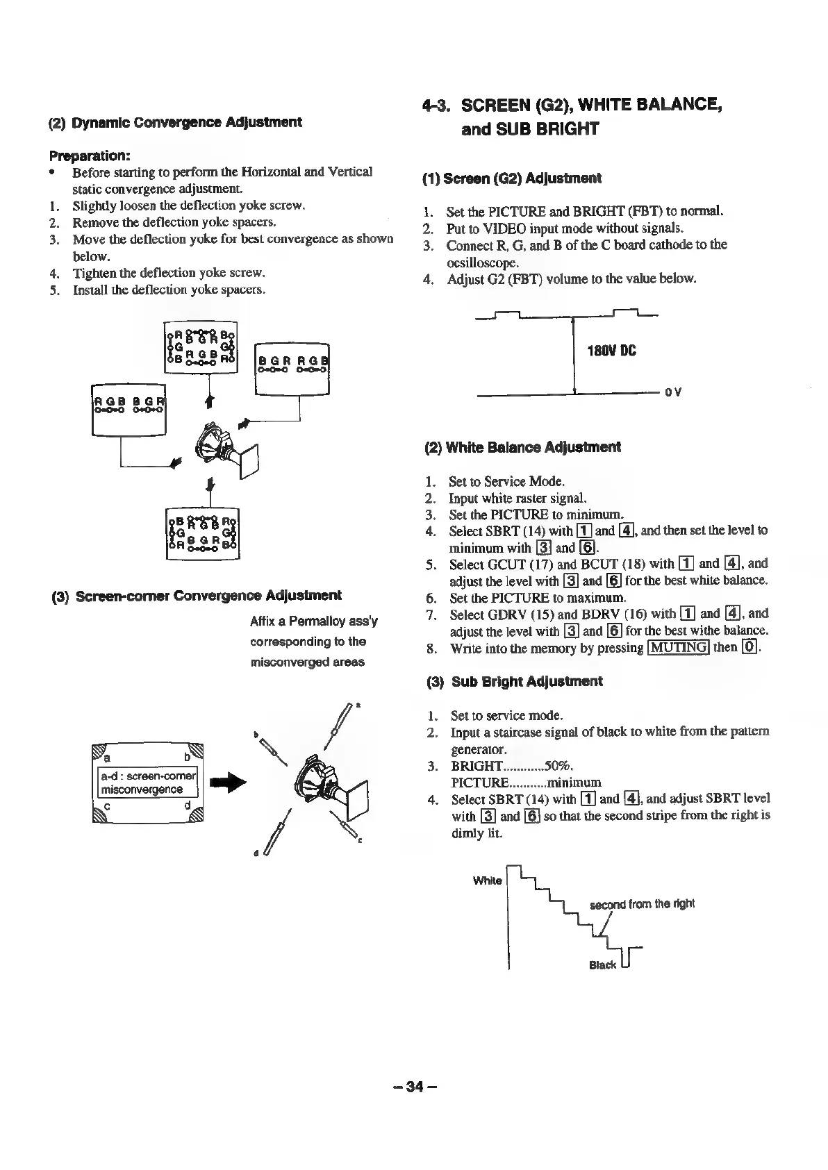
(2)
Dynamic
Convergence
Adjustment
P
.
oe
reparation:
Before
starting
to
perform
the
Horizontal
and
Vertical
static
convergence
adjustment.
Slightly
loosen
the
deflection
yoke
screw.
Remove
the
deflection
yoke
spacers.
Move
the
deflection
yoke
for
best
convergence
as
shown
below.
Tighten
the
deflection
yoke
screw.
Install
the
deflection
yoke
spacers.
REE
[ones
agp
aga
EEL
leseedl
(3)
Screen-corner
Convergence
Adjustment
Affix
a
Permalloy
ass'y
corresponding
to
the
misconverged
areas
of
\
>
Se
vA
a-d
:
screen-comer|
misconvergence
4-3.
SCREEN
(G2),
WHITE
BALANCE,
and
SUB
BRIGHT
(1)
Screen
(G2)
Adjustment
1.
3.
Set
the
PICTURE
and
BRIGHT
(FBT)
to
normal.
Put
to
VIDEO
input
mode
without
signals.
Connect
R,
G,
and
B
of
the
C
board
cathode
to
the
ocsilloscope.
Adjust
G2
(FBT)
volume
to
the
value
below.
180V
DC
ov
(2)
White
Balance
Adjustment
1.
Set
to
Service
Mode.
2.
Input
white
raster
signal.
3.
Set
the
PICTURE
to
minimum.
4.
Select
SBRT
(14)
with
[1]
and
[4],
and
then
set
the
level
to
minimum
with
[3]
and
[6].
5.
Select
GCUT
(17)
and
BCUT
(18)
with
[1]
and
[4],
and
adjust
the
level
with
[3]
and
[6]
for
the
best
white
balance.
6.
Set
the
PICTURE
to
maximum.
7.
Select
GDRV
(15)
and
BDRV
(16)
with
[1]
and
[4],
and
8.
adjust
the
level
with
[3]
and
[6]
for
the
best
withe
balance.
Write
into
the
memory
by
pressing
[MUTING]
then
fol.
(3)
Sub
Bright
Adjustment
-34-
Set
to
service
mode.
Input
a
staircase
signal
of
black
to
white
from
the
pattern
generator.
BRIGHT..
50%.
PICTURE.
minimum
Select
SBRT
(14)
with
[1]
and
[4],
and
adjust
SBRT
level
with
[3]
and
[6]
so
that
the
second
stripe
from
the
right
is
dimly
lit.
White
second
from
the
right
Black