EasyManua.ls Logo

Sony Trinitron KV-27XBR51 User Manual

Sony Trinitron KV-27XBR51
81 pages
To Next Page IconTo Next Page
Page #1 background imageLoading...
Page #1 background image
-
KV-27XBR51/27XBR55
RM-V'I
06
RM-V'I
07
SERVICE
MANUAL
US
Model
Television system
Channel coverage
Picture
lube
Antenna
Input
••••
•••
MICROFILM
KV-27XBR51
Chassis No. SCC·E28D·A
KV·27XBR55
Chassis No. SCC·E28A·A
Canadian Model
KV·27XBR51
Chassis No. SCC·E35D·A
~
ANu:lA
;~~~~~~
MODELS
OF
THE SAME SERIES
KV-27XBR51
/27XBR55
KV-27XBR50
KV-27XBR
10/27XBR60
KV-27XBR15/27XBR65
American TV standards
SPECIFICATIONS
Output
MONITOR OUTPUT
VHF: 2 -
13
UHF:
14
- 69
Cable
TV:
1 - 125
Microblack Trimtron tube
27-inch picture measured diagonally
28-inch picture tube measured di·
agonally
75-ohm external antenna terminal for
VHF/UHF
VIDEO
1,
2 and 3
IN
S VIDEO IN (4·pin mini DIN)
Y: 1
Vp-p,
75
ohms
unbalanced, sync negative
C: 0.286 Vp-p (Burst signal)
75·ohms
Video (phone jacks): 1 Vp·p,
75-ohms unbalanced, sync negative
Audio (phono jacks): 500 mVrms
(100% modulation)
Impedance: 47 kilohms
S VIDEO OUTPUT (4-pin mini DIN)
Y:
1
Vp-p,
75-ohms
unbalanced, sync negative
C: 0.286 Vp·p (Burst signal)
75-ohms
Video (phone jacks): 1 Vp-p,
7S·ohms unbalanced, sync negative
Audio (phone jacks): 500 mVrms
(100% modulation)
Impedance:
10
kilohms
AUDIO OUTPUT (VARIABLE) (phono
jacks)
More than 408 mVrms at the maximum
volume setting (variable)
Impedance: 5 kilohms
Speaker
output
Main speakers
SW
x
2:
8-0hm minimum
Super woofer
20W: 8-ohm minimum
Power
requirements
120V AC, 60Hz
Power
consumption
225W
(MAX)
l.5W (stand
by)
TRINITRON@
COLOR
TV
SONY
Question and Answer IconNeed help?

Do you have a question about the Sony Trinitron KV-27XBR51 and is the answer not in the manual?

Sony Trinitron KV-27XBR51 Specifications

General IconGeneral
Screen Size27 inches
Display TechnologyCRT
Resolution480i
Aspect Ratio4:3
Speakers2
InputsS-Video, RF
Audio Power10W x 2
Weight110 lbs (49.9 kg)

Summary

TV Safety Check-out Procedures

AC Leakage Testing Procedure

Procedure for testing AC leakage current from exposed metal parts to earth ground.

Proper Earth Grounding Method

Methodology for verifying proper earth ground connection using tools.

Section 1: General Information and Operations

Front and Rear Panel Parts Identification

Identification of front and rear panel components and terminals.

Automatic TV Channel Presetting

Instructions for automatically presetting receivable TV channels.

How to Watch TV Programs

Guide on how to select and watch TV channels using the remote.

Multi-Channel Viewing (Picture-in-Picture)

How to watch multiple channels or video sources simultaneously.

Advanced Window Picture Functions

Advanced operations for window picture display and memory.

Screen Setup and Clock Configuration

Adjusting screen parameters and setting the TV's clock.

Setting Timer-Activated Functions

Setting the ON/OFF timer for automatic program playback.

Favorite Channels and Channel Blocking Setup

Storing favorite channels and preventing specific channels from being viewed.

Programmable Remote Commander for External Devices

Operating Sony and non-Sony video equipment with the remote.

Section 2: Disassembly Procedures

Rear Cover and U Board Removal

Steps for removing the television's rear cover and U board.

TV Service Position Setup

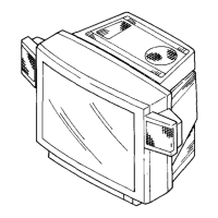
Instructions for placing the TV in a service-friendly position.

Picture Tube and Anode-Cap Removal

Procedures for removing the picture tube and handling the anode cap.

Section 3: Set-up and Picture Adjustments

Beam Landing and Purity Adjustment

Adjusting beam landing and purity for optimal picture display.

Color Convergence Adjustments

Performing static, dynamic, and screen-corner convergence adjustments.

Focus, White Balance, and Sub Adjustments

Adjusting focus, white balance, and sub brightness for picture quality.

Section 4: Critical Safety Adjustments

Safety Component Confirmation (R549, R567)

Hold-down confirmation and readjustment procedures for R549 and R567.

B+ Voltage Confirmation Procedure

Procedure for confirming B+ voltage after component replacement.

Section 5: Circuit Adjustments

Service Mode Entry and Remote Controls

Entering service mode and understanding remote commander controls.

Specific Circuit Adjustments (RF, Frequency, Chroma)

Detailed circuit adjustments for RF AGC, frequency, and chroma.

Board-Specific Circuit Adjustments (P, V)

Adjustments for P board (KV-27XBR55) and V board (KV-27XBR55).

Section 6: Diagrams and Component Identification

System Block Diagrams

Overall block diagrams illustrating signal flow and component interaction.

Circuit Board Layout Diagrams

Diagrams showing the physical layout of circuit boards within the TV.

Semiconductor Component Identification

Identification and pin views of various semiconductors used in the TV.

Section 7: Exploded Views

Chassis Exploded View and Parts

Exploded diagram of the TV chassis with numbered parts.

Picture Tube Assembly Exploded View

Exploded diagram of the picture tube assembly and related components.

Speaker Assembly Exploded View

Exploded diagram of the speaker assemblies and mounting hardware.

Section 8: Electrical Parts List

Electrical Parts List (B Board Components)

Detailed list of electrical components for the B board.

Accessory: Remote Commander Specifications

RM-Y106 Exploded View

Exploded view of the RM-Y106 remote commander.

RM-Y107 Exploded View

Exploded view of the RM-Y107 remote commander.

Related product manuals