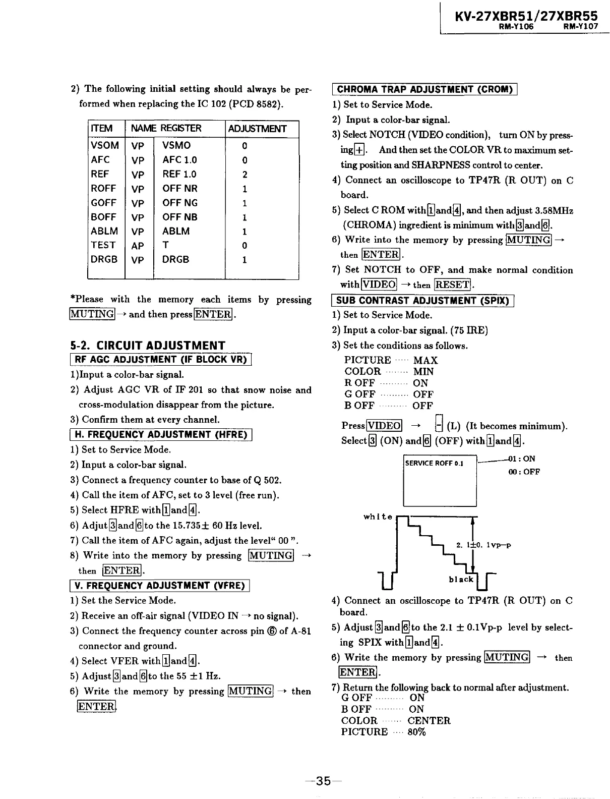
2)
The
following initial
setting
should always be per-
formed when replacing
the
IC 102
(PCD
8582).
ITEM
NAME
REGISTER
ADJUSTMENT
VSOM
VP
VSMO
0
AFC
VP
AFC 1.0
0
REF
VP
REF
1.0
2
ROFF
VP
OFFNR
1
GOFF
VP
OFF
NG
1
BOFF
VP
OFF
NB
1
ABLM
VP
ABLM
1
TEST
AP
T
0
DRGB
VP
DRGB
1
*Please with
the
memory each items by pressing
!MUTING!->
and
then
presslENTERI.
5-2. CIRCUIT ADJUSTMENT
I
RF
AGC
ADJUSTMENT (IF BLOCK VR) I
1
)Input
a color-bar signal.
2)
Adjust AGC
VR
of
IF
201
so
that
snow noise
and
cross-modulation disappear from
the
picture.
3) Confirm
them
at
every channel.
I
H.
FREQUENCY ADJUSTMENT (HFRE) I
1) Set
to
Service Mode.
2)
Input
a color-bar signal.
3) Connect a frequency
counter
to
base of Q 502.
4) Call
the
item
of
AFC,
set
to
3 level (free run).
5)
Select
HFRE
with[!]and~.
6)
Adjut@land~to
the
15.735±
60 Hz level.
7)
Call
the
item
of AFC again,
adjust
the
level"
00
".
8)
Write
into
the
memory by pressing !MUTING!
--->
then !ENTER!.
I
v.
FREQUENCY ADJUSTMENT (VFRE) I
1) Set
the
Service Mode.
2)
Receive
an
off-air signal (VIDEO
IN~•
no signal).
3) Connect
the
frequency
counter
across
pin®
of A-81
connector
and
ground.
4) Select
VFER
with[!]and~.
5)
Adjust@land~to
the
55
±1
Hz.
6)
Write
the
memory by pressing !MUTING!--->
then
!ENTER~
KV-27XBR51/27XBR55
RM-Y106 RM-Y107
I CHROMA TRAP ADJUSTMENT (CROM) I
1) Set
to
Service Mode.
2)
Input
a color-bar signal.
3)
Select NOTCH (VIDEO condition),
tum
ON by press-
ingl±J. And then set the COLOR
VR
to maximum set-
ting position and SHARPNESS control to center.
4) Connect
an
oscilloscope
to
TP47R
(R
OUT)
on
C
board.
5) Select
CROM
with[!]and~,
and
then adjust 3.58MHz
(CHROMA) ingredient
is
minimum
with@la.nd~.
6)
Write
into
the
memory
by
pressing !MUTING!--->
then !ENTER!.
7)
Set
NOTCH
to
OFF,
and
make normal condition
with!VIDEOI
--->then
!RESET!.
I SUB CONTRAST ADJUSTMENT (SPIX) I
1) Set
to
Service Mode.
2)
Input
a color-bar signal. (75
IRE)
3) Set
the
conditions as follows.
PICTURE
· · · · ·
MAX
COLOR
MIN
ROFF·
ON
GOFF·········
OFF
BOFF
·
OFF
PresslVIDEOI
--->
g (L)
(It
becomes minimum).
Select@] (ON)
and~
(OFF)
with[!]and~.
SERVICE
ROFF
0.1
,
___
,_-0..,1:
ON
OO:OFF
4) Connect
an
oscilloscope
to
TP47R
(R
OUT)
on C
board.
5)
Adjust@]and~to
the
2.1
±
0.lVp-p
level
by
select-
ing SPIX
with[!]and~.
6)
Write
the
memory by pressing !MUTING!
--->
then
!ENTER!.
7)
Return the following back
to
normal after adjustment.
GOFF·
ON
BOFF
· ON
COLOR·
CENTER
PICTURE
· 80%
-35-
 Loading...