22
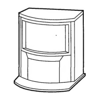
Fig 3-6
Note : If you are unable to adjust the corner convergence
properly, this can be corrected with the use of
permalloys.
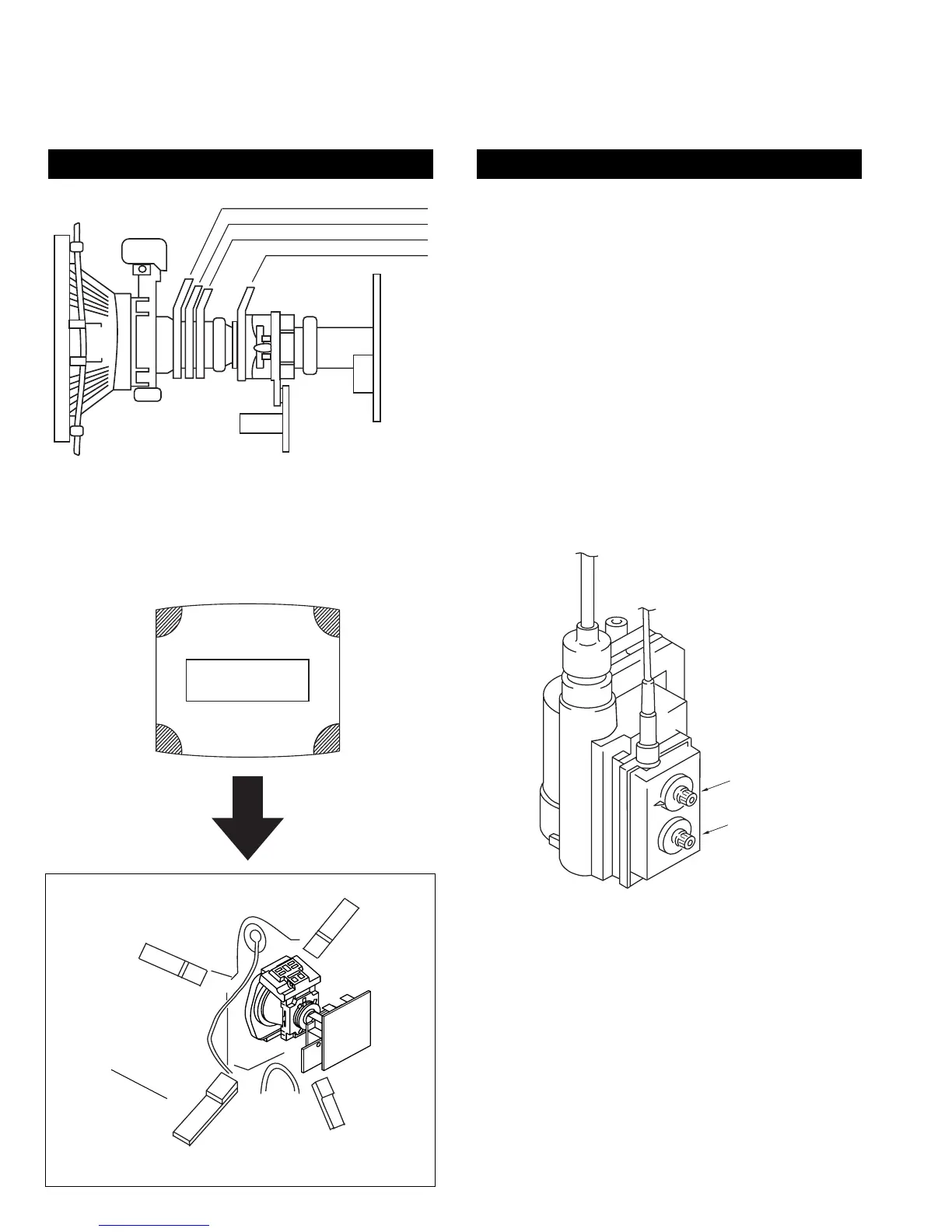
3-3.SCREEN (G2)
1. Input a dot signal from the pattern generator.
2. Set the Picture, Brightness and Colour to minimum.
3. Apply 175V DC from an external power supply to the
R, G and B cathodes of the CRT.
4. Whilst watching the picture, adjust [SCREEN G2] located on
the FBT [flyback transformer] to the point just before the
flyback return lines disappear.
3-4.FOCUS
1. Receive a television broadcast signal.
2. Normalise the picture setting.
3 Adjust the focus control located on the FBT [flyback
transformer] to obtain the best focus at the centre of the screen.
Bring only the centre area of the screen into focus, the
magenta-ring appears on the screen. In this case, adjust the
focus to optimize the screen uniformly.
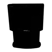
LAYOUT OF EACH CONTROL SCREEN G2 ADJUSTMENT
Y-splitting axis correction magnet
V STAT convergence magnet
BMC (Hexaploe) magnet
Purity magnet
a-d: screen-corner
convergence defect
a
b
c
d
Permalloy Assy
X-4387-214-1
Convergence adjustment with permalloy.
FOCUS
SCREEN (G2)