EasyManua.ls Logo

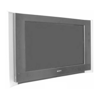
Sony Trinitron KV-32HS510 User Manual

Sony Trinitron KV-32HS510
376 pages
To Next Page IconTo Next Page
Page #1 background imageLoading...
Page #1 background image
TRINITRON
®
COLOR TELEVISION
SERVICE MANUAL
DA-4
CHASSIS
MODEL NAME REMOTE COMMANDER DESTINATION CHASSIS NO.
9-965-937-02
KV-32HS510
RM-Y190 US SCC-S66G-A
KV-32HS510
RM-Y190 CANADA SCC-S70F-A
KV-34DRC510
RM-Y190 LATIN NORTH SCC-S71F-A
KV-34DRC510
RM-Y190 LATIN SOUTH SCC-S71G-A
KV-34HS510
RM-Y191 US SCC-S66H-A
KV-34HS510
RM-Y191 CANADA SCC-S70G-A
KV-36HS510
RM-Y190 US SCC-S66J-A
KV-36HS510
RM-Y190 CANADA SCC-S70H-A
KV-36HS510
RM-Y190 HAWAII SCC-S69D-A
KV-38DRC510
RM-Y190 LATIN NORTH SCC-S71H-A
KV-38DRC510
RM-Y190 LATIN SOUTH SCC-S71J-A
HISTORY INFORMATION FOR THE FOLLOWING MANUAL:
ORIGINAL MANUAL ISSUE DATE: 3/2003
:CORRECTED ITEM
REVISION DATE REVISION TYPE SUBJECT
3/2003 No revisions or updates are applicable at this time.
6/2003 Correction - 1 Replaced P. 220 - J9001 added to CX Board Parts List.

Table of Contents

Question and Answer IconNeed help?

Do you have a question about the Sony Trinitron KV-32HS510 and is the answer not in the manual?

Sony Trinitron KV-32HS510 Specifications

General IconGeneral
BrandSony
ModelTrinitron KV-32HS510
CategoryTV
LanguageEnglish

Summary

Specifications

Warnings and Cautions

Safety Related Component Warning

Highlights critical components for safe operation and replacement guidelines.

Safety Check-Out

Leakage Test Procedure

Outlines the method for testing AC leakage from exposed metal parts to earth ground.

Self-Diagnostic Function

Diagnostic Test Indicators

Explains how the STANDBY/TIMER LED flashes indicate specific error causes.

Section 1: Disassembly

Anode Cap Removal Procedure

Step-by-step guide for removing the anode cap from the picture tube.

Section 2: Set-Up Adjustments

Beam Landing Adjustment

Detailed steps for adjusting beam landing for optimal convergence.

Section 3: Safety Related Adjustments

Preparation Before Confirmation

Standard settings and check conditions required before performing safety adjustments.

HV Service Flowchart

A troubleshooting flowchart for High Voltage (HV) service procedures.

Section 4: Circuit Adjustments

Setting Service Adjustment Mode

Instructions on how to enter and operate the service adjustment mode.

Service Data Lists

Comprehensive lists of service data parameters for various models.

Section 5: Diagrams

Block Diagrams

Illustrates the signal flow and functional blocks of the TV system.

Schematics and Supporting Information

Provides detailed schematic diagrams for various boards like D, M, U, etc.

Section 7: Electrical Parts List

Basic Connections: Connecting a Cable or Antenna

Connecting Optional Equipment

VCR and Cable Box

Instructions for connecting a VCR and cable box for optimal viewing.

Setting Up the Channel List

Steps for running Auto Setup to configure TV channels and reset to factory settings.

Related product manuals