– 12 –
KV-PG21P40/PG21M70/PG21P70
RM-952
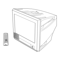
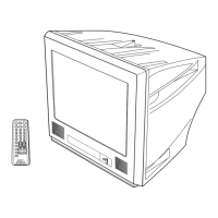
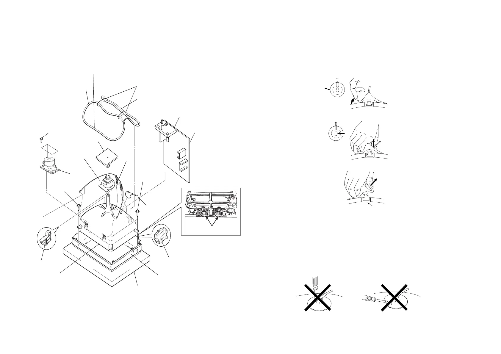
2-7. PICTURE TUBE REMOVAL
Note:
• Please make sure the TV set is not in standing position before removing necessary
CRT support located on bottom right and left.
!™
!£
8 Demagnetic coil
4 Four screws
(washer head)
(BVTP 3 × 12)
!º Two screws
(Tapping 5+
Crown Washer)
3 Speaker
(5 × 9cm)
6 Tension
spring
7 Chassis assy
5 Deflection
yoke
2 CV board
1 Anode cap
Coating earth assy
!∞ Picture tube
!¢ Cushion
9
Two screws
(Tapping 5 +
Crown Washer)
!¡
Holder DGC
Cushion (50x550) DGC
Cushion (35x250) DGC
A Board
CRT Support Block
Slim Beznet
CRT Support Block
Screw Location
• REMOVAL OF ANODE-CAP
NOTE : After removing the anode, short circuit the anode of the picture tube and
the anode cap to the metal chassis, CRT shield or carbon paint on the
CRT.
• REMOVING PROCEDURES
1 Turn up one side of the rubber cap in the direction indicated by the arrow a.
2 Using a thumb pull up the rubber cap firmly in the direction indicated by the arrow b.
3 When one side of the rubber cap is separated from the anode button, the anode-cap
can be removed by turning up the rubber cap and pulling it up in the direction of the
arrow c.
• HOW TO HANDLE AN ANODE-CAP
1 Do not damage the surface of anode-caps with sharp shaped objects.
2 Do not press the rubber too hard so as not to damage the inside of anode-cap.
A metal fitting called the shatter-hook terminal is built into the rubber.
3 Do not turn the foot of rubber over too hard.
The shatter-hook terminal will stick out or damage the rubber.