EasyManua.ls Logo

Sony trinitron PVM-1450QM User Manual

Sony trinitron PVM-1450QM
113 pages
To Next Page IconTo Next Page
Page #1 background imageLoading...
Page #1 background image
· SERVICE MANUAL
AEP Model
PVM-1450QM:
Chassis No. SCC-G62C-A
D
PVM-1454QM:
Chassis No. SCC-G628-A
PVM-1450QM
PVM-1454QM
SPECIFICATIONS (PVM-1450QM)
Video signal
Color system
Resolution
Aperture correction
Frequency response
PAL, SECAM, NTSC, NTSCw
450TV lines
0dB-+6.0dB
LINE 9.0 MHz (-3 dB)
RGB 10.0 MHz (-3 dB)
Synchronization AFC time constant 1.0 msec.
Pidure performance
Normal scan 7% over scan of CRT effective screen
area
H. linearity Less than 8.0% (typical)
V. linearity Less than 7.0% (typical)
Raster size stability H: 1.0%, V: 1.5%
High voltage regulation
3.5%
CRT P22 phosphor
Color temperature 6,SOOK
Inputs and Outputs
Inputs
Y IC IN: 4-pin mini DIN connector
(See the pin assignment.)
VIDEO IN: BNC connector
1Vp-p ±6 dB, sync negative
AUDIO IN: phono jack, -5 dBs, more
than 47k ohms
R, G, BIN: BNC connector
0.7 Vp,p, ±6 dB
Sync on green: 0.3 Vp-p, negative,
75 ohms terminated
RGB SYNC IN: BNC connector
Composite sync 4 Vp-p, ±6 dB,
negative
Loop-through outputs Y /C OUT: 4-pin mini DIN connector
VIDEO OUT: BNC connector,
75 ohms terminated
AUDIO OUT: phono jack
Speaker output Output level 0.8 W
General
Power consumption 90 Wh
Power requirements 100- 240 V AC, 50/60 Hz
Operating temperature range
0-35°C
Storage temperature range
-10-+40°C
Humidity 0 - 90%
Dimensions Approx. 346 x 340 x 411.5 mm
(w/h/d)
(13
5
/s x 131h x 16 ¼ inches)
not incl. projecting parts and controls
Mass Approx. 16.7 kg (36 lb 14 oz)
Accessory supplied AC power cord (1)
AC plug holder (1)
- Continued on page 2 -
TRINITRON@ COLOR VIDEO MONITOR
SO:NY:

Table of Contents

Question and Answer IconNeed help?

Do you have a question about the Sony trinitron PVM-1450QM and is the answer not in the manual?

Sony trinitron PVM-1450QM Specifications

General IconGeneral
BrandSony
Modeltrinitron PVM-1450QM
CategoryMonitor
LanguageEnglish

Summary

SPECIFICATIONS (PVM-1450QM)

Video Signal

Technical specifications for video signal input and processing.

Picture Performance

Performance characteristics of the monitor's display.

Inputs and Outputs

Details of the monitor's input and output connectors and signals.

General

General specifications and operating parameters of the monitor.

SPECIFICATIONS (PVM-1454QM)

Video Signal

Technical specifications for video signal input and processing.

Picture Performance

Performance characteristics of the monitor's display.

Inputs and Outputs

Details of the monitor's input and output connectors and signals.

General

General specifications and operating parameters of the monitor.

SECTION 1 GENERAL

PVM-1450QM Overview and Features

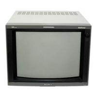
Overview of the PVM-1450QM model, including its features.

Location and Function of Parts and Controls

Front Panel Controls

Description of the monitor's front panel controls and their functions.

Rear Panel Connectors

Description of the monitor's rear panel connectors and their functions.

Input Selectors and Other Controls

Functions of selectors for 16:9, H/V Delay, Under Scan, Blue Only, EXT Sync, Line/RGB, C/SDI, B/Component, A/RGB.

Remote and Sync Connectors

Details on remote, RGB/Component, and external sync connectors.

On-Screen Menu Operations

Menu Navigation and Structure

Navigating the primary on-screen menu structure and accessing settings.

Button Functions and Menu Details

Explanation of menu buttons and details of specific menu options.

Power Sources

House Current Connection

Instructions for connecting the monitor to the AC power supply.

SECTION 1 GENERAL

1-2. GENERAL OF PVM-1454QM

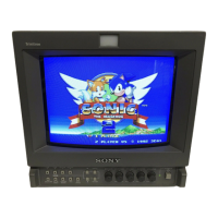
Overview of the PVM-1454QM model, including its features.

SECTION 2 DISASSEMBLY

Top Cover and Rear Cover Removal

Procedure for removing the top and rear covers of the monitor.

Terminal Board Removal

Steps for safely removing the terminal board.

Picture Tube Removal

Detailed instructions for removing the CRT picture tube.

SECTION 3 SET-UP ADJUSTMENTS

Preparations and Service Mode

Preparations for service mode and initial setup.

Model Data Writing, Picture Output, and Landing Adjustment

Procedures for writing model data, setting picture output, and adjusting landing.

Convergence Adjustment

Steps for aligning the R, G, B dots for precise convergence on screen.

Deflection Yoke Neck Rotation Adjustment

Procedure to reduce misconvergence by adjusting the deflection yoke neck rotation.

G2 and White Balance Adjustments

Adjusting G2 level and white balance using test signals and analyzers.

Blue-Only WB and Sub Brightness/Focus Adjustments

Adjusting white balance in blue-only mode, sub-brightness, and focus.

SECTION 4 SAFETY RELATED ADJUSTMENT

Voltage and Circuit Protection Adjustments

Safety adjustments for voltage detection, regulation, and circuit protection.

SECTION 5 CIRCUIT ADJUSTMENTS

A Board Adjustments

Adjustments performed on the A board using specific signals and test points.

Deflection System Adjustments

Horizontal Frequency, H-BLK, and Picture Phase Adjustments

Adjusting horizontal frequency, H-BLK, and picture phase for signal waveforms.

V-BLK Adjustments

Adjusting V-BLK for white frame alignment on PVM-1454QM and PVM-1450QM.

16:9 Aspect Ratio and Vertical Deflection Adjustments

Adjusting 16:9 BLK and vertical deflection section for aspect ratios.

Horizontal Deflection Section Adjustments

Adjusting horizontal size, pincushion, and bow distortion.

Under Scan, H/V Delay, and OSD Position Adjustments

Adjusting under scan, H/V delay, and OSD position for optimal display.

Writing Adjustment Results

Procedure for saving adjustment results into the monitor's memory.

SECTION III SIGNAL SYSTEM ADJUSTMENT

Normal/HV DL Sub-Control, Sub Phase, and Chroma Adjustments

Adjusting signal system parameters for various video inputs.

R-Y Level, Burst Gate, VXO, and NTSC Color Demodulation Adjustments

Adjusting signal system parameters for NTSC and color demodulation.

PAL Chroma, R-Y Level, and SECAM Adjustments

Adjusting signal parameters for PAL and SECAM video inputs.

NTSC 443 R-Y Level and PAL Phase Adjustments

Adjusting NTSC 443 R-Y level and PAL phase for optimal signal display.

SECTION 6 DIAGRAMS

Block Diagrams

High-level block diagram illustrating the monitor's functional units.

Frame Schematic Diagram (PVM-1454QM only)

Frame schematic diagram specific to the PVM-1454QM model.

Circuit Boards Location

Diagram showing the physical layout of the main circuit boards within the monitor.

Printed Wiring Boards and Schematic Diagrams

Detailed diagrams of printed wiring boards and their corresponding schematic layouts.

Semiconductors

List and diagrams of semiconductor components used in the monitor.

SECTION 7 EXPLODED VIEWS

Chassis Exploded View

Exploded view of the monitor's chassis and its constituent parts.

Picture Tube Exploded View

Exploded view of the CRT picture tube assembly and its components.

SECTION 8 ELECTRICAL PARTS LIST

A (PVM-1450QM) Parts List

Comprehensive list of electrical parts for the PVM-1450QM.

A (PVM-1454QM) Parts List

Comprehensive list of electrical parts for the PVM-1454QM.

SUPPLEMENT-1

Introduction

Introduction to the supplement, noting CE mark and G Block changes.

Related product manuals