EasyManuals Logo

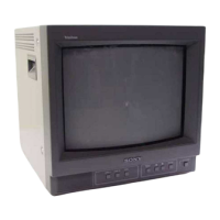
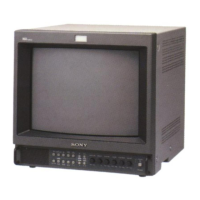
Sony Trinitron PVM-14N1E Service Manual

Sony Trinitron PVM-14N1E
59 pages
To Next Page IconTo Next Page
To Previous Page IconTo Previous Page
Page #6 background imageLoading...
Page #6 background image
Location
and
Function
of
Parts
and
Controls
QUNE
A
connectors
LINE
connectors
(SSM-14N1E/14N1U/20N1E/20N1U
only)
teu
4N1
E/14N1MDE/
4N1U/14N2A/1
4N2E/4
4N2U/20N1
A/20N1E/20N1U/20N2A/20N2E/
onl
Orcs
connectors
(PVM-14N1MDE
only)
@
REMOTE
connector
@n~ac
IN
connector
O
Ground
terminal
@-~ac
IN
connector
(The
“V\-
mark
indicates
automatic
termination.)
PVM-20N2A/20N2E/20N2U
rear
panel
@
LINE
A
connectors
(PVM-14N1A/14NIE/
14N1MDE/14N1U/14N2A/14N2E/14N2U/20N
1
A/
20N
LE/20N
1
U/20N2A/20N2E/20N2U
only)
LINE
connectors
(SSM-14N1E/14N1U/20N1E/
20N10U
only)
‘Input
connectors
for
the
composite
video,
Y/C
separate
video
and
audio
signals
and
their
loop-through
output
connectors.
To
monitor
the
input
signal
fed
through
these
connectors,
press
the
LINE
A
button
on
the
front
panel.
(PVM-14N1A/14N1E/14N1MDE/14N1U/
14N2A/14N2E/14N2U/20N
1
A/20N1E/20N
1U/
20N2A/20N2E/20N2U
ONLY)
The
Y/C
IN
connector
has
priority
over
the
VIDEO
IN
connector.
When
connecting
the
cable
to
the
Y/C
IN
connector,
the
Y/C
IN
connector
is
automatically
selected
and
the
VIDEO
IN
connector
is
disconnected
even
if
the
cable
is
connected.
Y/C
IN
connector
(4-pin
mini-DIN)
Connect
to
the
Y/C
separate
output
connector
of
a
video
camera,
VCR
or
other
video
equipment.
Y/C
OUT
connector
(4-pin
mini-DIN)
Loop-through
output
of
the
Y/C
IN
connector.
Connect
to
the
Y/C
separate
input
connector
of
a
VCR
or
another
monitor.
When
the
cable
is
connected
to
this
connector,
the
75-
ohm
termination
of
the
input
is
automatically
released,
and
the
signal
input
to
the
Y/C
IN
connector
is
output
from
this
connector.
VIDEO
IN
connector
(BNC-type)
Connect
to
the
video
output
connector
of
video
equipment,
such
as
a
VCR
or
a
color
video
camera.
For
a
loop-through
connection,
connect
to
the
video
output
connector
of
another
monitor.
VIDEO
OUT
connector
(BNC-type)
Loop-through
output
connector
of
the
VIDEO
IN
connector.
Connect
to
the
video
input
connector
for
a
VCR
or
another
monitor.
When
the
cable
is
connected
to
this
connector,
the
75-
ohm
termination
of
the
input
is
automatically
released,
and
the
signal
input
tothe
VIDEO
IN
connector
is
output
from
this
connector.
AUDIO
IN
connector
(phono
jack)
Connect
to
the
audio
output
connector
of
a
VCR
or
other
equipment.
For
a
loop-through
connection,
connect
to
the
audio
output
of
another
monitor.
AUDIO
OUT
connector
(phono
jack)
Loop-through
output
of
the
AUDIO
IN
connector.
Connect
to
the
audio
input
connector
of
a
VCR
or
another
monitor.
@
LINE
B
connectors
(PVM-14N1A/14N1E/
14N1MDE/14N1U/14N2A/14N2E/14N2U/20N
1
A/
20N
LE/20N
1U/20N2A/20N2E/20N2U
only)
Input
connectors
for
the
composite
video,
Y/C
separate
video
and
audio
signals.
To
monitor
the
input
signal
fed
through
these
connectors,
press
the
LINE
B
button
on
the
front
panel.
Y/C
IN
connector
(4-pin
mini-DIN)
Connect
to
the
Y/C
separate
output
connector
of
a
video
camera,
VCR
or
other
video
equipment.
VIDEO
IN
connector
(BNC-type)
Connect
to
the
video
output
connector
of
video
equipment,
such
as
a
VCR
or
a
color
video
camera.
For
a
loop-through
connection,
connect
to
the
video
output
connector
of
another
monitor.
AUDIO
IN
connector
(phono
jack)
Connect
to
the
audio
output
connector
of
a
VCR
or
other
equipment.
For
a
loop-through
connection,
connect
to
the
audio
output
of
another
monitor.
©
RGB
connectors
(provided
with
the
PVM-14N2A/14N2E/
14N2U
/20N2A/20N2E/20N2U
only)
Analog
RGB
input
connectors
for the
R/G/B
signals,
external
sync
signals
and
audio
signals.
To
monitor
the
input
signal
fed
through
these
connectors,
press
the
RGB
button
on
the
front
panel.
R/G/B
(input)
connectors
(BNC-type)
Connect
to
the
analog
RGB
outputs
connectors
of
a
video
camera,
VCR
or
other
video
equipment.
The
monitor
operates
on
the
external
sync
signal.
The
monitor
also-can
operate
on
the
sync
signal
from
the
G
channel
by
setting
RGB
SYNC
to
SYNC
ON
GREEN
in
the
menu.
For
detailed
information
on
sync
signal
setting,
see
“Bal
RGB
SYNC
menu
"on
page
12
of
“Functions
of
On-Screen
Menus”.
AUDIO
IN
connector
(phono
jack)
Connect
to
the
audio
output
connectors
of
video
equipment
when
the
analog
RGB
signal
is
input.
EXT
SYNC
(external
sync
input)
connector
(BNC-type)
Connect
to
the
sync
signal
output
of
a
video
camera,
VCR
or
other
video
equipment.
When
you
set
RGB
SYNC
to
SYNC
ON
GREEN
in
the
menu,
the
monitor
operates
on
the
sync
signal
from
the
G
channel
so
that
it
is
not
necessary
to
use
this
connector.
For
detailed
information
on
sync
signal
setting,
see
“Bal
RGB
SYNC
menu
"on
page
12
of
“Functions
of
On-Screen
Menus”.
©
REMOTE
connector
(phono
jack)
(provided
with
the
PVM-14N2A/14N2E/
14N2U
/20N2A/20N2E/20N2U
only)
This
connector
functions
as
follows.
Open:
When
this
connector
is
open,
the
current
input
signal
is
selected.
Ground:
By
grounding
this
connector,
the
input
signal
selected
before
this
current
signal
is
selected.
©
~AC
IN
(inlet)
connector
Connect
the
supplied
AC
power
cord
to
this
connector
and
to
a
wall
outlet.
©
Ground
(¥)
terminal
(provided
with
the
PVM-14N1MDE
only)
Connect
a
GND
cable.

Other manuals for Sony Trinitron PVM-14N1E

Questions and Answers:

Question and Answer IconNeed help?

Do you have a question about the Sony Trinitron PVM-14N1E and is the answer not in the manual?

Sony Trinitron PVM-14N1E Specifications

General IconGeneral
BrandSony
ModelTrinitron PVM-14N1E
CategoryMonitor
LanguageEnglish

Related product manuals