PVM-2950Q/2950QM
RM-854
SECTION 3
SET-UP ADJUSTMENTS
• Carry out the following adjustments when readjustment is
required or when attaching a new picture tube.
• These adjustments should be carried out at rated power supply
voltage unless otherwise specified.
Controls and switches should be set in standard position as listed
below unless otherwise specified.
Contrast · · · · · · · · · · Standard
Brightness· · · · · · · · · · Standard
3-1. BEAM LANDING
Preparations
l. Face the picture tube screen of the set in an eastward or
westward direction to reduce the influence of earth
magnetism.
2. Tum the power switch on the set to ON to carry out
demagnetizing.
( 1) Adjustment of the Y separation axis correction magnet.
1. Receive the image of the crosshatch.
2. Adjust the picture to minimum and the brightness to
standard.
3. Secure the neck assembly to the position shown in the
figure (Fig. 3-2).
4. Move the DY until it comes in contact with the CRT and
set it in a upright position.
5. Open and close the Y separation axis correction magnet on
the neck assembly until there is up-down symmetry and
adjust so that the upper and lower pins are symmetrical.
6. Return the DY to the original position.
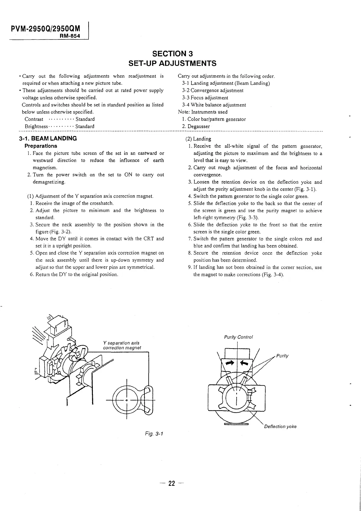
Y separation axis
correction magnet
Fig. 3-1
Carry out adjustments in the following order.
3-1 Landing adjustment (Beam Landing)
3-2 Convergence adjustment
3-3 Focus adjustment
3-4 White balance adjustment
Note: Instruments used
1. Color bar/pattern generator
2. Degausser
(2) Landing
1. Receive the all-white signal of the pattern generator,
adjusting the picture to maximum and the brightness to a
level that is easy to view.
2. Carry out rough adjustment of the focus and horizontal
convergence.
3. Loosen the retention device on the deflection yoke and
adjust the purity adjustment knob in the center (Fig. 3-1 ).
4. Switch the pattern generator to the single color green.
5. Slide the deflection yoke to the back so that the center of
the screen is green and use the purity magnet to achieve
left-right symmetry (Fig. 3-3).
6. Slide the deflection yoke to the front so that the entire
screen is the single color green.
7. Switch the pattern generator to the single colors red and
blue and confirm that landing has been obtained.
8. Secure the retention device once the deflection yoke
position has been determined.
9. If landing has not been obtained in the comer section, use
the magnet to make corrections (Fig. 3-4).
Purity Control
Purity
Deflection yoke