EasyManua.ls Logo

Sony Trinitron PVM-2950QM User Manual

Sony Trinitron PVM-2950QM
104 pages
To Next Page IconTo Next Page
Page #1 background imageLoading...
Page #1 background image
11111111111111111111111111111111111111
(13711
PVM-29500/2950QM
,.
RM-854
SERVICE MANUAL
US Model
Canadian Model
Video signal
Picture tube
Color system
00 C,
PVM-2950Q
Chassis No. SCC-G61E-A
AEP Model
PVM-2950QM
Chassis No. SCC-G62D-A
Aus Model
PVM-2950QM
Chassis No. SCC-H03B-A
MODELS OF THE SAME SERIES
PVM-2950Q/2950QM
SPECIFICATIONS
Picture performance
29" Su per T rinitron tube Color temperature
Visible picture size : 675 mm
(27" measured diagonally) Line pull range
AG pitch : 0.70 - 0.85 mm
Anti-glare &. Anti-static Overscan
NTSC, PAL, SECAM, NTSC4.43, PAL60 Zooming
9300K/6500K (standard)/3200K
switchable
Horizontal : ± 500 Hz
Vertical : -8 Hz
7% preset ( ±3% variable)
Within 5%
Resolution 600 TV lines at the center
Frequency response VIDEO: 7 MHz (-3 dB)
S VIDEO: 8 MHz (-3 dB)
RGB: 10 MHz (-3 dB)
- Continued on next page -
TRINITRON®COLOR VIDEO MONITOR
SONY
Question and Answer IconNeed help?

Do you have a question about the Sony Trinitron PVM-2950QM and is the answer not in the manual?

Sony Trinitron PVM-2950QM Specifications

General IconGeneral
Screen Size29 inches
Aspect Ratio4:3
ResolutionUp to 800 TV lines
Refresh Rate50/60 Hz
Display TypeCRT
TechnologyTrinitron
Input ConnectorsBNC
Audio InputsRCA
Scan Lines625

Summary

SPECIFICATIONS

General Information

Safety Warnings and Precautions

SAFETY CHECK-OUT

LEAKAGE TEST

Procedures and limits for checking AC leakage current from exposed metal parts.

HOW TO FIND A GOOD EARTH GROUND

Methods for identifying a proper earth ground connection for safety tests.

SECTION 1 GENERAL

Features Overview

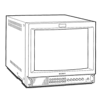
Key capabilities and technologies: Trinitron tube, multi-system, index number, menus, input types.

Location and Function of Parts and Controls

Remote Commander Operation

Remote Commander Controls

Explains the function of each button on the remote commander.

SECTION 3 SET-UP ADJUSTMENTS

BEAM LANDING

Procedure for adjusting beam landing and purity for optimal picture geometry.

SECTION 2 DISASSEMBLY

CONVERGENCE ADJUSTMENT

Screen Center Convergence Adjustment

Detailed steps for static convergence adjustment in the screen center.
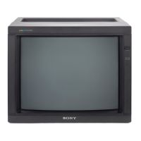
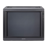
Dynamic Convergence Adjustment

FOCUS ADJUSTMENT

WHITE BALANCE ADJUSTMENT

SECTION 4 SAFETY RELATED ADJUSTMENTS

SECTION 5 ELECTRIC ADJUSTMENT IN THE SERVICE MODE

SECTION 6 CIRCUIT ADJUSTMENTS

Chroma Decoder Adjustment

NTSC Hue/Color Adjustment

PAL Color Demodulation Adjustment

Line Crawling Adjustment

SECAM Bell Filter Adjustment

A BOARD ADJUSTMENT

UT BOARD ADJUSTMENT

VC BOARD ADJUSTMENT

SEMICONDUCTORS

SECTION 8 EXPLODED VIEWS

SECTION 9 ELECTRICAL PARTS LIST

Related product manuals