I
z
3
4
5
6
,_
1
,_
2
,_
3
,_
4
s
6
-
7
-
8
-
9
-
I
14
,._
- N
.---
UJ UJ
IOOOV
zoov
E
-~
CN704
HI
ZP
H2
WHT
:MINI
CN703
bP
WHT
:MINI-
-·-.
,c
(RGB oun
L_
-
-
I
15
I
I
KG KB GZ Fl~--
tt t 1./
I, 1r==t==tvso1
H_-~ Lj::::!~'-
1 I II I
J 11 1_:_ 1 PICTURE
TUBE
t t I t ,
CV KR GI G4 HV 1'----
\
--
R
I
G
2
a
3
E
4
H.BL
I( 5
V.BL
I( 6
IK.RT
N 7
+12
V 8
CN702
BP
~ff
:S-HICRO
;---CN-901- --- - --- - 7-
9P
WHT
:S-HICRO
I
+B
z
+B
3
E
4
IZV
5 VM OUT
I
6
VM MUTE
7 Q.P.+
NC
8
V
Q.P.-9
L ___
<VM AMPJ
I
-
I
B-55321 B<U/C>-KESSENZU
-51-
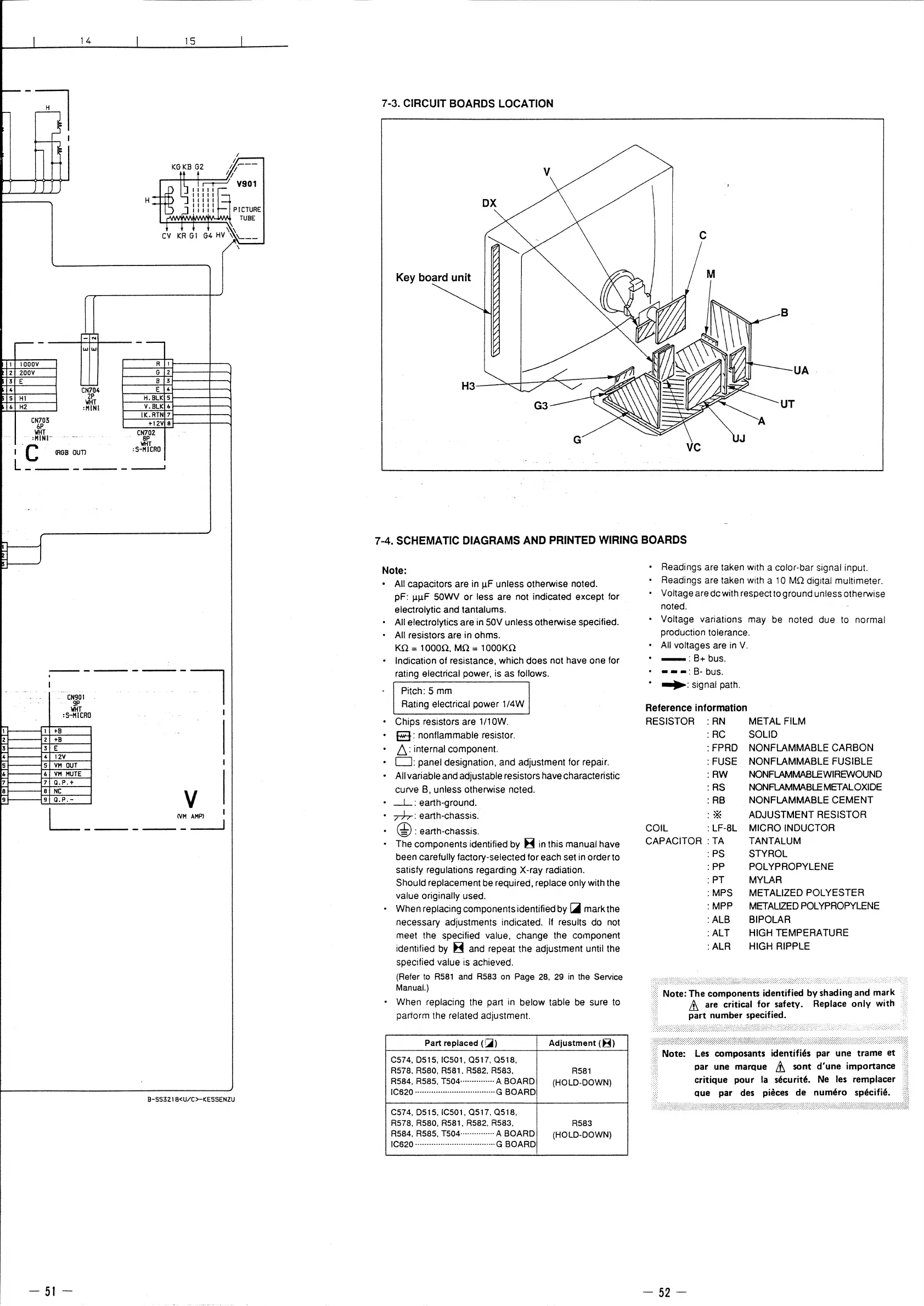
7-3. CIRCUIT BOARDS LOCATION
V
Key board unit
UA
H3
vc
7-4. SCHEMATIC DIAGRAMS AND PRINTED WIRING BOARDS
Note:
• All capacitors are in µF unless otherwise noted.
pf: µµF SOWV or less are not indicated except for
electrolytic and tantalums.
• All electro!ytics are in 50V unless otherwise specified.
• All resistors are in ohms.
Kn = 1 ooon. Mn = 1 oooKn
• Indication of resistance, which does not have one for
rating electrical power, is as follows.
Pitch: 5 mm
Rating electrical power 1/4W
• Chips resistors are 1 /1 OW.
• E3: nonflammable resistor.
· 6: internal component.
• D: panel designation, and adjustment for repair.
• All variable and adjustable resistors have characteristic
curve B, unless otherwise noted.
• _L: earth-ground.
• Th-: earth-chassis.
• @ : earth-chassis.
• The components identified by B in this manual have
been carefully factory-selected for each set in order to
satisfy regulations regarding X-ray radiation.
Should replacement be required, replace only with the
value originally used.
When replacing components identified by c;jjjjl mark the
necessary adjustments indicated. If results do not
meet the specified value, change the component
identified by B and repeat the adjustment until the
specified value is achieved.
(Refer to R581 and R583 on Page 28, 29 in the Service
Manual.)
When replacing the part in below table be sure to
pariorm the related adjustment.
Part replaced (!::;ii) Adjustment ( 8)
C574, D515, IC501, 0517, 0518,
R578,R580,R581,R582,R583,
R581
R584, R585, T504··············· A BOARD
(HOLD-DOWN)
IC620 ···································G BOARD
C574, D515, IC501, 0517, 0518,
R578, RSB0, R581, R582, R583,
R583
R584, R585, T504··············· A BOARD
(HOLD-DOWN)
IC620 ···································G BOARD
• Readings are taken with a color-bar signal input.
Readings are taken with a 10 Mn digital multimeter.
Voltage are dcwith respect to ground unless otherwise
noted.
• Voltage variations may be noted due to normal
production tolerance.
• All voltages are in V.
• -: B+ bus.
• • - •: B- bus.
• .._.: signal path.
Reference information
RESISTOR : AN MET AL FILM
: AC SOLID
: FPAD NONFLAMMABLE CARBON
:FUSE
NONFLAMMABLE FUSIBLE
:AW
NONFLAMMABLEWIAEWOUND
: RS
NONFLAMMABLE METAL OXIDE
: AB
NONFLAMMABLE CEMENT
:*
ADJUSTMENT RESISTOR
COIL
: LF-8L MICRO INDUCTOR
CAPACITOR : TA TANTALUM
- 52 -
:PS STYROL
:PP POL YPAOPYLENE
: PT MYLAR
: MPS METALIZED POLYESTER
: MPP
METALIZED POLYPROPYLENE
:ALB BIPOLAR
:ALT
HIGH TEMPERATURE
:ALA
HIGH RIPPLE
Les composants identifies par une trame et
par une marque &, sont d'une importance
critique pour la securite. Ne les remplacer
aue par des pieces de numero specifie.
 Loading...