PVM-2950Q/2950QM
RM-854
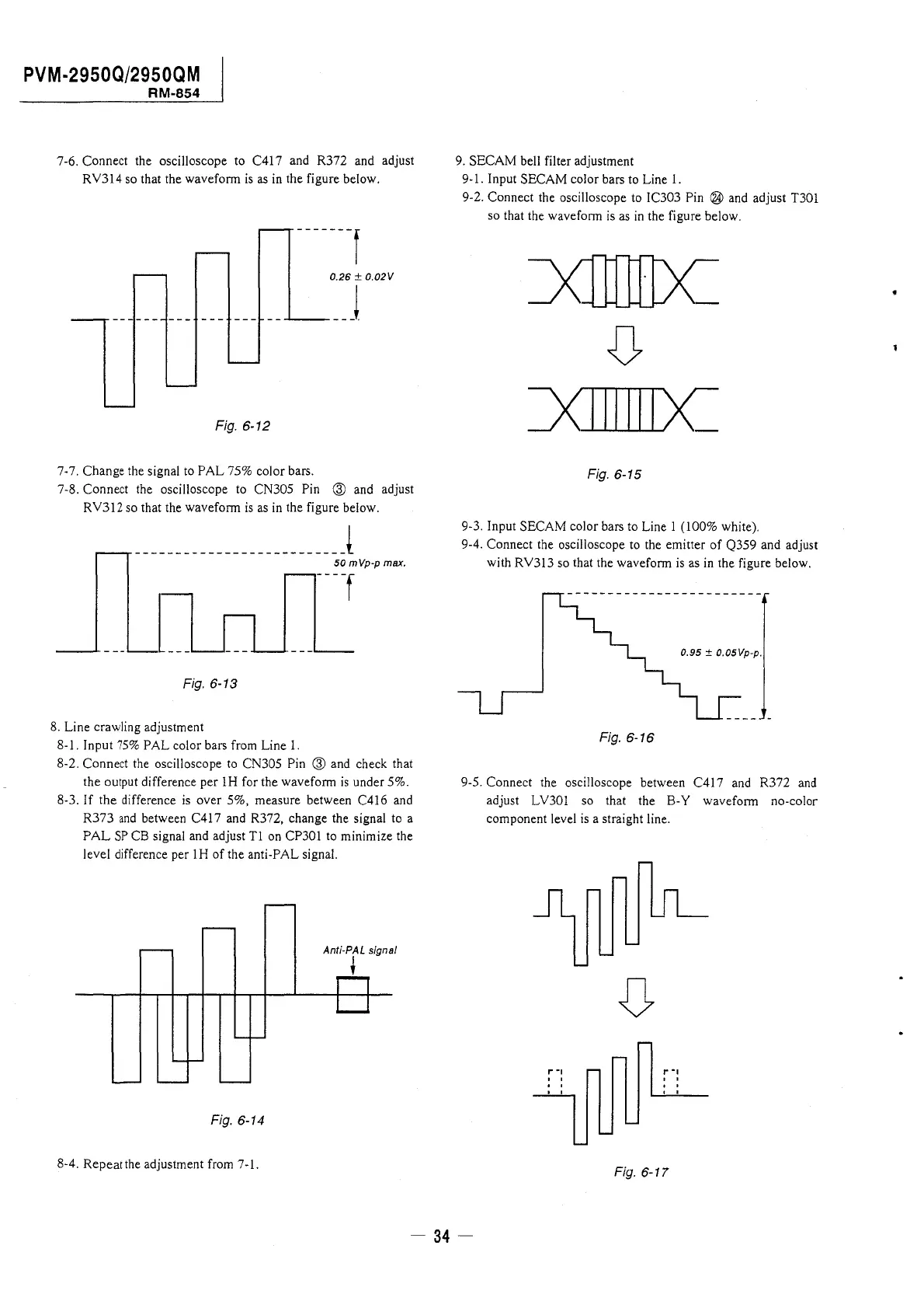
7-6. Connect the oscilloscope to C417 and R372 and adjust
RY314 so that the waveform is as in the figure below.
-------f
0.26 ± 0.02V
---------------__ ...,_____ __ j
Fig. 6-12
7-7. Change the signal to PAL 75% color bars.
7-8. Connect the oscilloscope to CN305 Pin @ and adjust
RY312 so that the waveform is as in the figure below.
__________________________ l
50 mVp-p max.
[ --
Fig. 6-13
8. Line crawling adjustment
8-1. Input 75% PAL color bars from Line 1.
8-2. Connect the oscilloscope to CN305 Pin @ and check that
the output difference per lH for the waveform is under 5%.
8-3. If the difference is over 5%, measure between C416 and
R373 and between C417 and R372, change the signal to a
PAL SP CB signal and adjust Tl on CP301 to minimize the
level difference per lH of the anti-PAL signal.
Anti-PAL signal
t
Fig. 6-14
8-4. Repeat the adjustment from 7-1.
9. SECAM bell filter adjustment
9-1. Input SECAM color bars to Line 1.
9-2. Connect the oscilloscope to IC303 Pin ® and adjust T301
so that the waveform is as in the figure below.
Fig. 6-15
9-3. Input SECAM color bars to Line 1 (100% white).
9-4. Connect the oscilloscope to the emitter of Q359 and adjust
with RY313 so that the waveform is as in the figure below.
0.95 ± 0.05Vp-p.
Fig. 6-16
9-5. Connect the oscilloscope between C417 and R372 and
adjust LY301 so that the B-Y waveform no-color
component level is a straight line.
,..,
I"-,
' '
' '
' '
Fig. 6-17
- 34-
 Loading...