Do you have a question about the Sony UP-X898MD and is the answer not in the manual?
Explains the manual's focus on board replacement for service engineers.
Lists the "Instructions for Use CD-ROM" as an additional resource.
Identifies registered and unregistered trademarks used within the manual.
Provides a diagnostic flowchart to guide service procedures, covering pre and post-service steps.
Instructions for safe handling and transport to prevent unit damage.
Illustrates the physical placement of internal boards and key components.
Specifies torque values for screws during assembly and disassembly.
Detailed steps for accessing internal components by removing the casing.
Introduction to the PC-based utility software for diagnostics and settings.
Step-by-step guide to update the printer's firmware using the utility.
Instructions on entering and using the unit's service mode for direct operations.
Procedure to lock/unlock front panel controls to prevent unintended changes.
Information on the internal battery and its replacement schedule.
Procedures for cleaning internal and external parts of the printer.
Lists parts requiring regular inspection or replacement.
Details standard print dimensions for video and digital inputs.
Guidelines for using lead-free solder during repair work.
Method to retrieve and analyze error logs for fault diagnosis.
Comprehensive list of error codes, their symptoms, causes, and remedies.
Diagnostic flowcharts to systematically identify and resolve issues.
Troubleshooting steps for failures when the power switch is turned on.
Diagnosing issues with front panel controls and indicators.
Resolving PC connectivity and printing problems.
Troubleshooting issues specific to video signal input printing.
Diagnosing print distortions caused by irregular paper feeding.
Steps to adjust print density settings for optimal output quality.
Troubleshooting errors related to the paper feed mechanism.
Diagnosing problems with the thermal head's vertical movement system.
Troubleshooting issues concerning the printer's door mechanism.
Diagnosing and resolving errors with paper detection sensors.
Troubleshooting the unit's internal real-time clock function.
Resolving issues with remote control or foot switch functionality.
Troubleshooting problems with saving print data to USB flash drives.
Procedures for replacing the main control board (MA-195).
Procedures for replacing the front panel interface board (KY-711).
Procedures for replacing the SE-1142 sensor board.
Procedures for replacing the SE-1143 sensor board.
Procedures for replacing the power supply switching regulator.
Procedures for replacing the MD general assembly.
Procedures for replacing the thermal print head.
Procedures for replacing motor assemblies.
Procedures for replacing the cam assembly.
Procedures for replacing the platen roller.
Procedures for replacing the timing belts.
Procedures for replacing the pinch arm block assembly.
Performing self-diagnosis tests on the unit.
General overview of the unit's electrical circuit components.
Detailed functions and blocks of the main control board.
Functions of the key button and sensor board.
Functions of the SE-1142 sensor and relay board.
Functions of the SE-1143 sensor board.
Function of the SU-167 board for DC motor control.
Important guidelines and warnings regarding spare parts.
Visual breakdown of the unit's components with part numbers.
Exploded view of the top cover and door panel assembly for UP-D898MD.
Exploded view of the top cover and door panel assembly for UP-X898MD.
Exploded view of the front panel assembly components.
Exploded view of the first mecha deck block components.
Exploded view of the second mecha deck block components.
Exploded view of the third mecha deck block components.
List of items included in the package with the unit.
Block diagram illustrating the overall system architecture.
Diagram showing the internal wiring connections of the unit.
| Color | No |
|---|---|
| Resolution | 162.5 lpi |
| Control type | Buttons, Rotary |
| Certification | (US/CA) ANSI/AAMI ES60601-1, UL 60601-1, UL 60950-1, CAN/CSA-C22.2 No.60601-1, CAN/CSA C22.2 No.601.1, CAN/CSA C22.2 No.60950-1 (EU) EN 60601-1, EN 60950-1 (CB) IEC 60601-1 (2nd/3rd Ed.), IEC 60950-1 (US/CA) FCC Part 15 Subpart-B Digital Device Class A, ICES-003 Class A Digital Apparatus (EU) EN 60601-1-2 (Class B), EN 55022 (Class B)+EN 55024, EN 61000-3-2+ EN 61000-3-3 (AU) AS/NZS CISPR22 (EN55022) Class B (JP) VCCI Class A, JIS C 61000-3-2 (KR) KN22, KN24 Class B (EU) MDD, EMC, LVD |
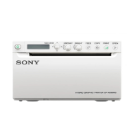
| Product color | White |
| Printing colors | Black |
| Built-in display | Yes |
| Grayscale levels | 256 |
| Print technology | Direct thermal printing |
| Printing time (max) | 1.9 s |
| Printing time (min) | 3.3 s |
| Maximum printing width | 110 mm |
| Analog signal format system | NTSC, PAL |
| USB 2.0 ports quantity | 1 |
| Power source | AC |
| AC input voltage | 100-240 V |
| AC input frequency | 50 - 60 Hz |
| Input current (max) | 1.3 A |
| Input current (min) | 0.6 A |
| Windows operating systems supported | Windows 7 Enterprise, Windows 7 Enterprise x64, Windows 7 Home Basic, Windows 7 Home Basic x64, Windows 7 Home Premium, Windows 7 Home Premium x64, Windows 7 Professional, Windows 7 Professional x64, Windows 7 Starter, Windows 7 Starter x64, Windows 7 Ultimate, Windows 7 Ultimate x64, Windows 8, Windows 8 Enterprise, Windows 8 Enterprise x64, Windows 8 Pro, Windows 8 Pro x64, Windows 8 x64, Windows Vista Business, Windows Vista Business x64, Windows Vista Enterprise, Windows Vista Enterprise x64, Windows Vista Home Basic, Windows Vista Home Basic x64, Windows Vista Home Premium, Windows Vista Home Premium x64, Windows Vista Ultimate, Windows Vista Ultimate x64, Windows XP Home, Windows XP Home x64, Windows XP Professional, Windows XP Professional x64 |
| Storage temperature (T-T) | -20 - 60 °C |
| Operating temperature (T-T) | 5 - 40 °C |
| Operating relative humidity (H-H) | 20 - 80 % |
| Cables included | USB |
| Depth | 240 mm |
|---|---|
| Width | 154 mm |
| Height | 88 mm |
| Weight | 2500 g |