


D
DeusAug 28, 2025
My UD-897MD printer beeps twice when i press the copy button and does not print
My UD-897MD printer beeps twice when i press the copy button and does not print
I have a sony UD-897MD
Explains the scope and content of the service manual for the UP-D897.
Lists other manuals provided with the unit for comprehensive information.
Identifies the physical placement of circuit boards within the unit.
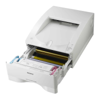
Shows the main internal components and their positions.
Provides instructions for disassembling and reassembling the printer's outer casing.
Details the procedure for removing and installing the top cover.
Explains how to remove and install the front panel assembly.
Outlines the steps for removing and installing the rear panel.
Guides on replacing key internal components of the printer.
Step-by-step guide for replacing the switching regulator and DC fan.
Procedure for removing and installing the mechanical deck assembly.
Instructions for replacing the thermal head component.
Details the removal and installation of stepping and DC motors.
Steps for removing and installing the cam shaft assembly.
Procedure for replacing the pinch arm assembly.
Instructions for replacing the platen roller.
Guide for removing and installing the timing belt.
Table detailing required processes for specific part replacements.
Information and precautions regarding the use of unleaded solder.
Outlines procedures for user setting record printing and factory reset.
Steps to print the unit's current user settings before adjustments.
Procedure to verify and adjust settings after performing maintenance.
Instructions to reset the unit to its original factory default settings.
Guide for calibrating brightness/contrast and checking button conductivity.
Procedure for adjusting head voltage after component replacement.
Steps to reset the printer's internal print count history.
Instructions for upgrading the printer's firmware.
Overview of the system's central control architecture and components.
Describes the main functions and blocks of the system control.
Provides a high-level block diagram of the electrical system.
Details the control mechanisms for the printer's mechanical parts and head.
General description of the head/mechanical control block.
Explains how the platen motor is controlled for rotation and speed.
Describes the control of the thermal head's vertical movement.
How the door position sensor is monitored.
Explains the paper detection mechanism.
Details the head temperature monitoring system.
Information on the head fan motor operation.
Explains how front panel buttons are read and processed.
Description of the unit's USB interface.
Detailed breakdown of the thermal head's operation and components.
Describes the physical structure of the thermal head.
Explains the fundamental operational principles of the thermal head.
Details how temperature variations affect print quality and are corrected.
Explains the mechanism for correcting errors caused by resistor variations.
Troubleshooting flowchart for unsatisfactory print results.
Flowchart for diagnosing issues with print density.
Diagnostic steps for paper detection errors.
Troubleshooting guide for thermal head vertical movement issues.
Flowchart for diagnosing paper feeding problems.
Steps to troubleshoot door open/close detection errors.
Instructions for entering the service mode.
Overview of the available diagnostic functions and menu structure.
Guide for printing various test patterns for diagnosis.
How to set the number of test patterns to be printed.
Procedure to check the functionality of the LCD lighting.
Instructions for verifying LED indicator lights.
Steps for calibrating front panel volume controls.
How to print system logs and error information.
Procedures for resetting various unit settings.
How to display the unit's current temperature.
Description of the FEED button's function in service mode.
How to lock and unlock the unit's settings and controls.
Important notes and warnings regarding spare parts.
Visual diagrams showing the assembly of major parts.
Comprehensive list of electrical components used in the unit.
Lists the accessories provided with the printer.
High-level functional block diagram of the entire system.
Table of contents for the schematic diagrams.
| printing method | Direct Thermal Printing |
|---|---|
| thermal head | Thin film thermal 1280 dots |
| resolution | 325 dpi |
| effective print pixels | 4096 x 1280 (max.) |
| interface | USB 2.0 High Speed Interface |
|---|---|
| memory | 4096 x 1280 x 8 bit |
| print speed | Approximately 2.0 seconds (High Speed Mode) |
|---|---|
| gradations | True 256 gray balance |
| dimensions | 154mm x 88mm x 240mm (WHD) |
|---|---|
| weight | Approximately 2.6kg |