Do you have a question about the Sony UP-D898MD and is the answer not in the manual?
Provides step-by-step guidance for diagnosing and resolving printer issues before service.
Details essential precautions to prevent damage when moving or shipping the printer unit.
Illustrates the physical placement of internal circuit boards and key components within the printer.
Specifies the correct torque values for various screws used in the printer assembly and disassembly.
Provides step-by-step instructions for removing and reinstalling the printer's outer cabinet parts.
Explains the requirements, setup, and functions of the utility software for printer maintenance.
Details the procedure for updating the printer's firmware using the utility software.
Explains how to enter and navigate the printer's service mode for advanced functions.
Describes how to lock and unlock the printer's operational controls to prevent unintended changes.
Information on the lithium battery, its replacement interval, and specifications for the UP-X898MD.
Instructions for cleaning the printer's exterior cabinet, thermal head, and platen roller.
Lists parts requiring regular inspection and replacement, including their recommended intervals.
Details the standard print sizes for video and digital input signals, including tolerances.
Guidelines and precautions for using lead-free solder during repair work on the unit's boards.
Explains how to obtain and interpret error logs for diagnosing printer malfunctions.
A table listing error codes, their symptoms, possible causes, and recommended remedies.
Diagnostic flowcharts to help identify and resolve specific printer operational problems.
Detailed procedures for replacing the MA-195 main board, including saving settings.
Instructions for removing and installing the KY-711 board, which includes the LCD and controls.
Steps for replacing the SE-1142 board, which contains various sensor circuits.
Procedure for removing and installing the SE-1143 board, also involved with sensor functions.
Guidance on replacing the switching regulator and resetting power on time.
Steps for removing and installing the main mechanical deck assembly.
Comprehensive guide for replacing the thermal head, including checks and adjustments.
Instructions for the removal and installation of the stepping motor and DC motor assemblies.
Procedures for removing and installing the cam assembly, including lubrication points.
Steps for removing and installing the platen roller, including cleaning advice.
Detailed instructions for removing and installing the various timing belts in the unit.
Guidance on replacing the pinch arm block assembly and associated parts.
Procedures for performing self-diagnosis tests using the utility software to check unit status.
Overview of the unit's electrical circuits and the main boards involved.
Detailed description of the functions and blocks integrated into the MA-195 main board.
Explanation of the KY-711 board's functions, including its LCD and sensor circuits.
Description of the sensor circuits and relay functions on the SE-1142 board.
Description of the sensor circuits mounted on the SE-1143 board.
Specifies the SU-167 board's role in fixing the DC motor.
Important notes regarding safety, standardization, stock, and symbols for spare parts.
Illustrated diagrams showing the assembly of the top cover and door panel block.
Lists the contents of the packing materials and accessories supplied with the unit.
A block diagram illustrating the overall system connections and major components of the unit.
Detailed wiring diagrams showing the connections between all internal electronic components and boards.
| Color | No |
|---|---|
| Resolution | 162.5 lpi |
| Control type | Buttons, Rotary |
| Certification | (US/CA) ANSI/AAMI ES60601-1, UL 60601-1, UL 60950-1, CAN/CSA-C22.2 No.60601-1, CAN/CSA C22.2 No.601.1, CAN/CSA C22.2 No.60950-1 (EU) EN 60601-1, EN 60950-1 (CB) IEC 60601-1 (2nd/3rd Ed.), IEC 60950-1 (US/CA) FCC Part 15 Subpart-B Digital Device Class A, ICES-003 Class A Digital Apparatus (EU) EN 60601-1-2 (Class B), EN 55022 (Class B)+EN 55024, EN 61000-3-2+ EN 61000-3-3 (AU) AS/NZS CISPR22 (EN55022) Class B (JP) VCCI Class A, JIS C 61000-3-2 (KR) KN22, KN24 Class B (EU) MDD, EMC, LVD |
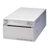
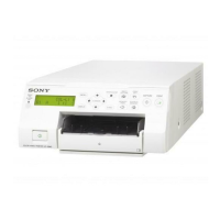
| Product color | White |
| Printing colors | Black |
| Built-in display | Yes |
| Grayscale levels | 256 |
| Print technology | Direct thermal printing |
| Printing time (max) | 1.9 s |
| Printing time (min) | 3.3 s |
| USB 2.0 ports quantity | 1 |
| Power source | AC |
| AC input voltage | 100-240 V |
| AC input frequency | 50 - 60 Hz |
| Input current (max) | 1.3 A |
| Input current (min) | 0.6 A |
| Windows operating systems supported | Windows 7 Enterprise, Windows 7 Enterprise x64, Windows 7 Home Basic, Windows 7 Home Basic x64, Windows 7 Home Premium, Windows 7 Home Premium x64, Windows 7 Professional, Windows 7 Professional x64, Windows 7 Starter, Windows 7 Starter x64, Windows 7 Ultimate, Windows 7 Ultimate x64, Windows 8, Windows 8 Enterprise, Windows 8 Enterprise x64, Windows 8 Pro, Windows 8 Pro x64, Windows 8 x64, Windows Vista Business, Windows Vista Business x64, Windows Vista Enterprise, Windows Vista Enterprise x64, Windows Vista Home Basic, Windows Vista Home Basic x64, Windows Vista Home Premium, Windows Vista Home Premium x64, Windows Vista Ultimate, Windows Vista Ultimate x64, Windows XP Home, Windows XP Home x64, Windows XP Professional, Windows XP Professional x64 |
| Storage temperature (T-T) | -20 - 60 °C |
| Operating temperature (T-T) | 5 - 40 °C |
| Operating relative humidity (H-H) | 20 - 80 % |
| Depth | 240 mm |
|---|---|
| Width | 154 mm |
| Height | 88 mm |
| Weight | 2500 g |