1 (E)
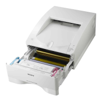
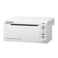
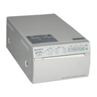
UP-D898MD/X898MD
Table of Contents
Manual Structure
Purpose of this manual ............................................................ 3 (E)
Related manuals ...................................................................... 3 (E)
Trademarks .............................................................................. 3 (E)
1. Service Overview
1-1. Service Flow Chart ....................................................1-1 (E)
1-1-1. Flow Chart before Service ...............................1-1 (E)
1-1-2. Flow Chart after Service .................................. 1-3 (E)
1-2. Precaution for Transporting ....................................... 1-4 (E)
1-3. Board Location and Main Parts Location .................1-5 (E)
1-3-1. Board Location ................................................1-5 (E)
1-3-2. Main Parts Location .........................................1-5 (E)
1-3-3. Sensor Location ...............................................1-6 (E)
1-4. Tightening torque ......................................................1-6 (E)
1-5. Removing/Installing the Cabinet ...............................1-7 (E)
1-5-1. Top Cover ........................................................1-7 (E)
1-5-2. Front Panel Block Assembly ...........................1-8 (E)
1-5-3. Rear Panel ......................................................1-10 (E)
1-6. General Information of Utility Software ................. 1-11 (E)
1-6-1. Required Equipment/Tools ............................ 1-11 (E)
1-6-2. Preparation ..................................................... 1-11 (E)
1-6-3. Function Description......................................1-12 (E)
1-7. Firmware Version Upgrade .....................................1-21 (E)
1-8. Service Mode...........................................................1-22 (E)
1-8-1. Startup Procedure ...........................................1-22 (E)
1-8-2. Service Mode Menu ....................................... 1-22 (E)
1-9. Menu Lock Function ...............................................1-26 (E)
1-10. Lithium Battery (UP-X898MD) .............................. 1-27 (E)
1-11. Cleaning ..................................................................1-28 (E)
1-11-1. Cleaning the Cabinet ......................................1-28 (E)
1-11-2. Cleaning the thermal head ............................. 1-28 (E)
1-11-3. Cleaning the Platen Roller .............................1-29 (E)
1-12. Periodic Inspection and Periodic
Replacement Parts ................................................... 1-30 (E)
1-13. Print Size .................................................................1-30 (E)
1-13-1. Rough Standard of Print Size.........................1-30 (E)
1-13-2. Interval Between Print Screens ......................1-31 (E)
1-13-3. Blank in Horizontal Direction........................1-31 (E)
1-14. Lead-free Solder ...................................................... 1-31 (E)
2. Troubleshooting
2-1. Error Log Acquisition Procedure ..............................2-1 (E)
2-1-1. Error Code Table .............................................. 2-1 (E)
2-2. Trouble Flow Chart ...................................................2-3 (E)
2-2-1. Power does not turn on even though the
power switch is turned on ................................2-3 (E)
2-2-2. Keys and LEDs on the front panel cannot be
controlled normally .......................................... 2-4 (E)
2-2-3. Printing cannot be performed normally from
PC or no image is output .................................. 2-5 (E)
2-2-4. Printing cannot be performed normally from
video signal
(NTSC/PAL) (UP-X898MD Only) .................. 2-7 (E)
2-2-5. Print image is distorted in the paper feed
direction (irregular feeding) .............................2-8 (E)
2-2-6. Print density is too high or too low .................. 2-9 (E)
2-2-7. Feed operation failure ....................................2-10 (E)
2-2-8. Thermal head UP/DOWN operation
failure ............................................................. 2-11 (E)
2-2-9. Door open/close operation failure..................2-12 (E)
2-2-10. Printing paper presence/absence sensor
failure .............................................................2-13 (E)
2-2-11. Real time clock does not operate normally
(UP-X898MD only) .......................................2-14 (E)
2-2-12. Remote terminal does not operate normally
(UP-X898MD only) .......................................2-14 (E)
2-2-13. Image is not written in the USB flash memory
after printing (UP-X898MD only) ................. 2-15 (E)
3. Replacement of Board and Main Parts
3-1. MA-195 Board .......................................................... 3-2 (E)
3-1-1. Flow Chart .......................................................3-2 (E)
3-1-2. Saving of Setting Value .................................... 3-3 (E)
3-1-3. Sample (Step) Printing ..................................... 3-4 (E)
3-1-4. Replacement Procedures of MA-195 Board .... 3-5 (E)
3-1-5. Setting and Check of Setting Value .................3-7 (E)
3-1-6. Density Adjustment (Thermal Head Voltage
Adjustment) and Set Serial Number Setting .... 3-8 (E)
3-2. KY-711 Board..........................................................3-10 (E)
3-3. SE-1142 Board ........................................................3-12 (E)
3-4. SE-1143 Board ........................................................3-13 (E)