3-18 (E)
UP-D898MD/X898MD
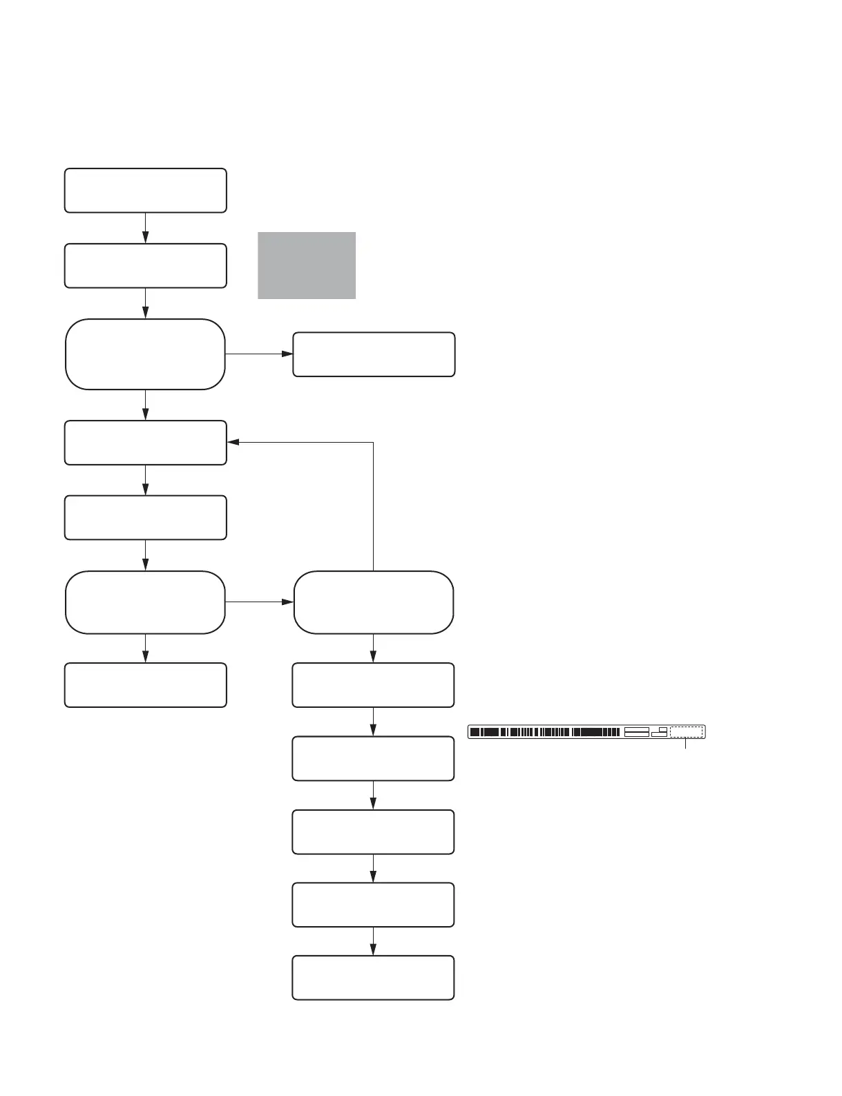
3-7-1. Replacement Flow Chart
When replacing the thermal head, be sure to perform the following procedure.
Start
End
Are there any streaks (white or
black) and scratches in the
paper feed direction?
No
Yes
Perform the cleaning of thermal
head. (Refer to Section 1-11-2.)
Did the streaks and scratches
disappear?
No
Yes No
Yes
Improved?
Replace the thermal head.
(Refer to Section 3-7-3.)
Perform the check.
(Refer to Section 3-13.)
Perform “3-7-4. Density Adjustment
(Thermal Head Voltage Adjustment)”.
Perform “3-7-5. Input of Thermal
Head Information and Reset of Total
Print Count”.
End
&
The resistance value of the heater portion varies depending
on the thermal head.
Even though the head voltage is the same, the energy to be
applied varies individually.
When replacing the thermal head, perform the voltage
adjustment of thermal head because the density of print before
and after replacement should be the same.
$
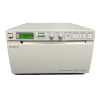
When replacing with the new thermal head, write down the
head resistance value (.e.g. R13152) and serial number
(e.g.3C-00121) indicated on the attached label before attaching it.
End
3C-00121
Head resistance value
Perform “3-7-2. Sample (Gray)
Printing”.
Perform “3-7-2. Sample (Gray)
Printing”.