3-2 (E)
UP-D898MD/X898MD
3-1. MA-195 Board
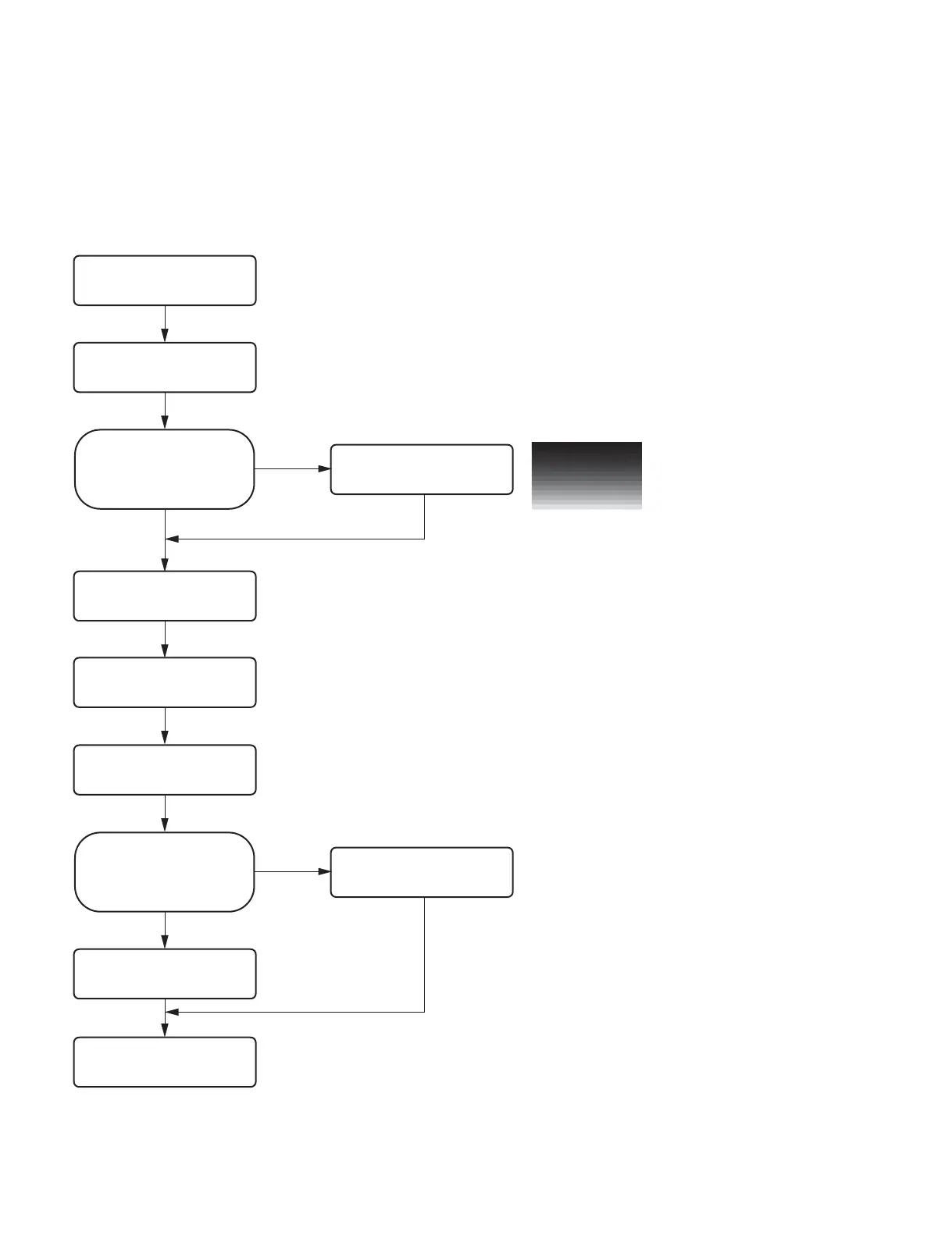
3-1-1. Flow Chart
In the MA-195 board, the adjustment value is stored in EEPROM (IC507) and the firmware is stored in
the flash ROM (IC503). When replacing the MA-195 board, perform the following procedure.
Start
Perform “3-1-2. Saving of Setting
Value.
Perform “3-1-3. Sample (Step)
Printing”.
Could the setting value be saved
before replacing the MA-195
board?
No
Yes
Replace the MA-195 board.
(Refer to Section 3-1-4.)
Perform the firmware version
upgrade. (Refer to Section 1-7.)
Perform the check.
(Refer to Section 3-13.)
Could the setting value be saved?
Perform “3-1-6. Density Adjustment
(Thermal Head Voltage Adjustment)
and Set Serial Number Setting”.
No
Yes
End
&
If the thermal head voltage setting value of the MA-195 board before
replacement could not be obtained, it is required to adjust the thermal
head voltage value because the print density before and after the
replacement should be the same.
Perform “3-1-5. Setting and
Check of Setting Value”.