2-9 (E)
UP-D898MD/X898MD
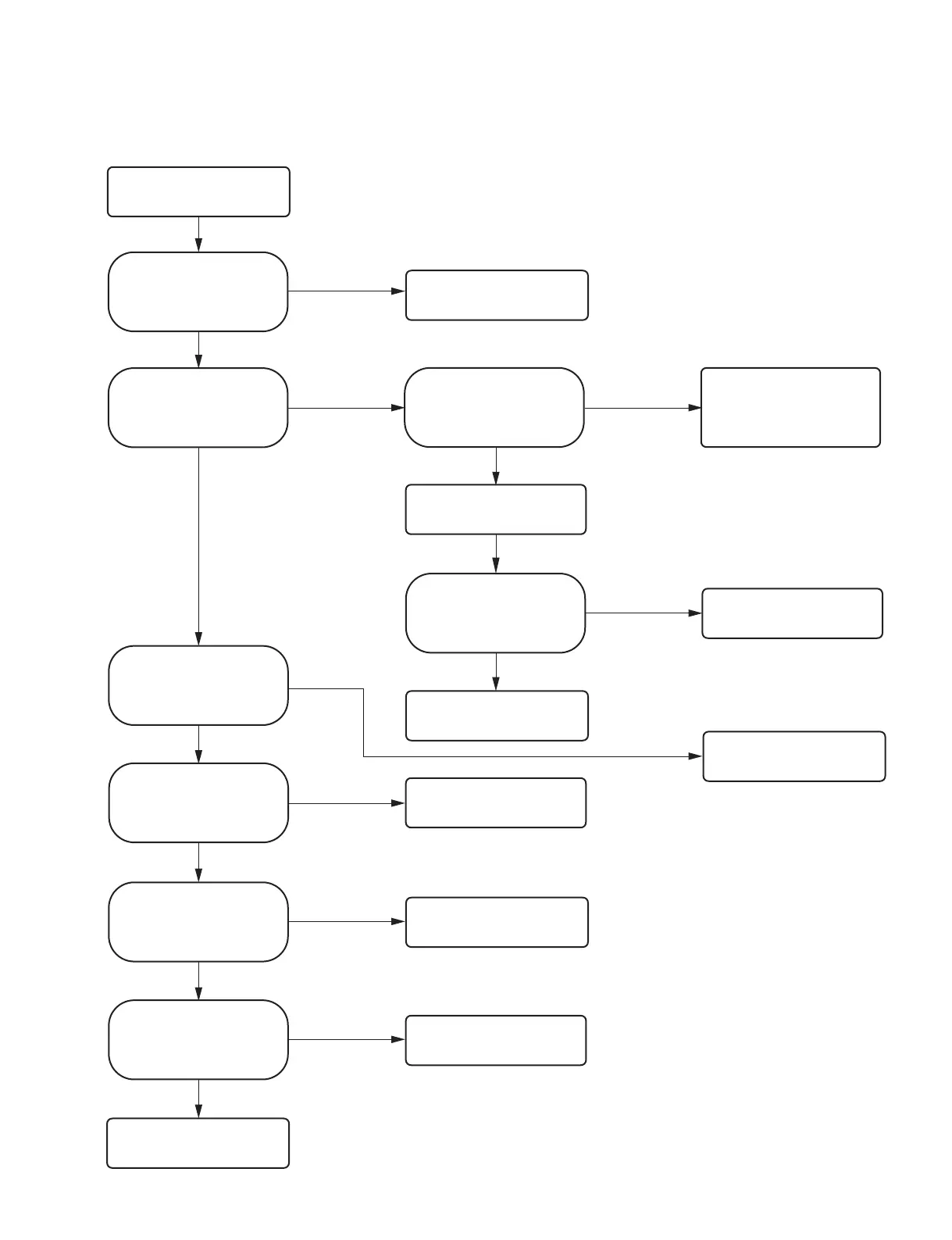
2-2-6. Print density is too high or too low
No
Yes Yes
No
Yes
No
Yes
No
No
Yes
Is the voltage at pins 1 and 2 (VH)
of CN101 on the MA-195 board
set to the head voltage setting
value during printing?
No
Yes
No
Yes
No
Yes
Replace the MA-195 board.
(Refer to Section 3-1.)
Print density is too high or too low.
FFC: Flexible flat cable
Is the voltage at pins 1 and 2 of
CN101 on the MA-195 board
changed to less than 1 V during
standby and to 25 V or more
during printing?
Is the voltage at pin 29
(THERMISTER) of CN701 on the
MA-195 board approx. 2.0 V to
2.4 V when the temperature is
25"C?
Replace the MA-195 board.
(Refer to Section 3-1.)
Is the pin 30 FFC connecting
CN701 on the MA-195 board and
thermal head connected correctly?
Check the connection of FFC.
If the symptom persists, replace
FFC. (Refer to Section 5.)
Replace the thermal head.
(Refer to Section 3-7.)
Again, is the voltage at pin 29
(THERMISTER) of CN701 on the
MA-195 board or CL712 (THERM)
approx. 2.0 V to 2.4 V when the
temperature is 25"C?
Replace the MA-195 board.
(Refer to Section 3-1.)
Normal
Is the density of sample print
normal?
Is the head voltage setting for the
thermal head resistance value
appropriate?
Replace the MA-195 board.
(Refer to Section 3-1.)
Replace the MA-195 board.
(Refer to Section 3-1.)
Set the thermal head voltage
value appropriately.
Replace the switching regulator.
(Refer to Section 3-5.)
Is the voltage at pin 3 (VCONT)
of CN101 on the MA-195 board
set to the voltage corresponding to
the head voltage setting value
during printing?
Relational expression: VH = 6 ) VCONT + 25 V (VCONT 0.8 V, VH tolerance:3%)