55
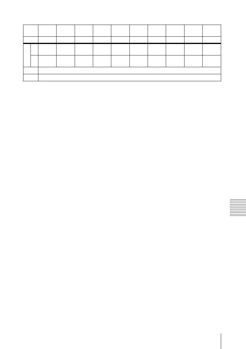
Installation Diagram
Others
a’(N) = {(PS × 29.415) × 1.03} - 32.0 + 16.4
a’(M) = {(PS × 35.283) × 0.97} - 32.0 + 16.4
x = b + {PS × 5.073 + (a’+ 32.0 - 16.4) × 0.07344 - 2.3 + 72.5}
The alphabetical letters in the charts and calculation methods indicate the following.
PS: projected image size measured diagonally
a’: distance between the hole (front) for mounting a projector suspension support on bottom
surface of this projector and the center of the screen
b: distance between the projector suspension support mounting surface on bottom of this
projector and the ceiling
x: distance between the center of the screen and the ceiling
N: minimum
M: maximum
Unit: mm (inches)
PS
(inches)
40 60 80 100 120 150 180 200 250 300
(mm) 1016 1524 2032 2540 3048 3810 4572 5080 6350 7620
a’ N 1200
(47
1
/
4
)
1800
(70
7
/
8
)
2410
(95)
3010
(118
5
/
8
)
3620
(142
5
/
8
)
4530
(178
3
/
8
)
5440
(214
1
/
4
)
6040
(237
7
/
8
)
7560
(297
3
/
4
)
9070
(357
1
/
4
)
M 1350
(53
1
/
4
)
2040
(80
3
/
8
)
2720
(107
1
/
8
)
3410
(134
3
/
8
)
4090
(161
1
/
8
)
5120
(201
5
/
8
)
6140
(241
7
/
8
)
6830
(269)
8540
(336
3
/
8
)
10250
(403
5
/
8
)
x Based on the calculation formula given below.
b Free