screw
(M1.4
×
5.0)
JIG
AUDIO board
0
!¡
!™
!£
!¢
!∞
!§
!¶
9
8
7
6
5
4
3
2
1
SECTION 1
GENERAL
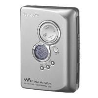
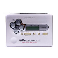
• LOCATION OF CONTROLS
SECTION 2
SERVICE NOTE
• Regarding the method of adjustment and voltage check, perform sections 3-1 and 3-2 of the DISASSEMBLY, and attach the JIG (extension
cable) to the AUDIO board as shown below.
JIG Part No.: J-2503-005-A
1 OPEN knob
2 Display window
3 PRESET + /AMS FF (Fast Forward) button
4 TUNING + button
5 TUNING – button
6 ENTER button
7 PRESET – /AMS REW (Rewind) button
8 MENU button
9 RADIO ON/BAND button
!º SET button
!¡ p /RADIO OFF button
!™ “” /REPEAT button
!£ VOLUME control
!¢ C HOLD knob
!∞ 2 REMOTE jack
!§ Battery case
!¶ DC IN 1.5V jack
 Loading...