— 2 —
Notes on chip component replacement
• Never reuse a disconnected chip component.
• Notice that the minus side of a tantalum capacitor may be
damaged by heat.
Flexible Circuit Board Repairing
• Keep the temperature of soldering iron around 270˚C
during repairing.
• Do not touch the soldering iron on the same conductor of the
circuit board (within 3 times).
• Be careful not to apply force on the conductor when soldering
or unsoldering.
TABLE OF CONTENTS
1. GENERAL ·········································································· 2
2. SERVICE NOTE ······························································· 3
3. DISASSEMBLY
3-1. Lid Block Assy, Cassette ················································ 5
3-2. Case Block Assy ····························································· 5
3-3. Ornament (Open) Block Assy ········································· 6
3-4. “Switch, Leaf (S704)”, Main Board ······························· 6
3-5. Belt (F0), Motor (M601)················································· 7
3-6. Holder (FA) Assy ···························································· 7
3-7. Pinch Lever (NF)/(RF) Assy ··········································· 8
3-8. Head, Magnetic (HP701) ················································ 8
4. MECHANICAL ADJUSTMENT ·································· 9
5. ELECTRICAL ADJUSTMENT ···································· 9
6. DIAGRAMS
6-1. Block Diagram ······························································ 10
6-2. Printed Wiring Board ···················································· 12
6-3. Schematic Diagram (1/2) ·············································· 15
6-4. Schematic Diagram (2/2) ·············································· 18
6-5. IC Block Diagrams ······················································· 21
6-6. IC Pin Function Description ········································· 23
7. EXPLODED VIEWS
7-1. Cabinet Block ······························································· 24
7-2. Mechanism Deck Block ················································ 25
8. ELECTRICAL PARTS LIST ······································· 26
SAFETY-RELATED COMPONENT WARNING!!
COMPONENTS IDENTIFIED BY MARK 0 OR DOTTED LINE WITH
MARK 0 ON THE SCHEMATIC DIAGRAMS AND IN THE PARTS
LIST ARE CRITICAL TO SAFE OPERATION. REPLACE THESE
COMPONENTS WITH SONY PARTS WHOSE PART NUMBERS
APPEAR AS SHOWN IN THIS MANUAL OR IN SUPPLEMENTS
PUBLISHED BY SONY.
SECTION 1
GENERAL
This section is extracted
from instruction manual.
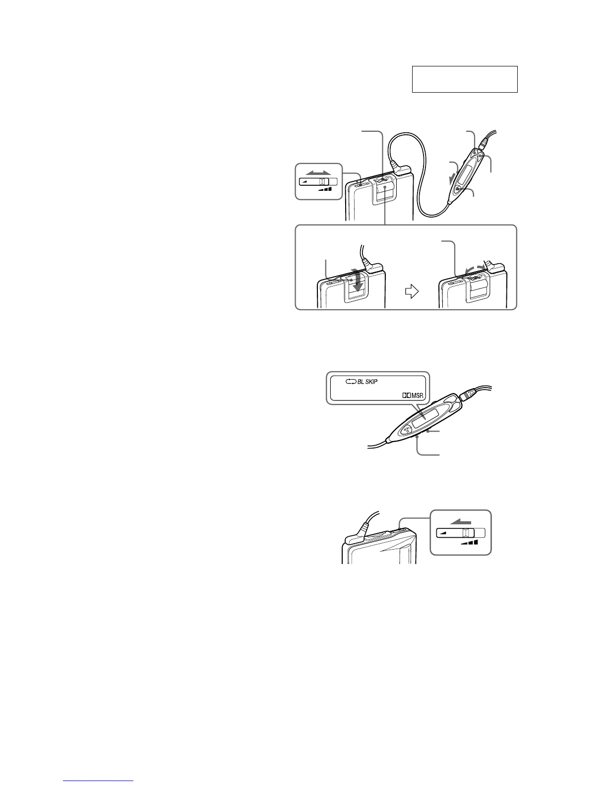
MODE
SOUND
VOL
AVLS
HOLD
Hold shutter
Cache de
verrouillage
Schutzschieber
VOL
AVLS
REW (–)
FF (+)
Y•x
Jog lever
Levier Jog
Jog-Hebel
FF
REW
Jog lever
Levier Jog
Jog-Hebel
Plug in firmly.
Branchez fermement.
Fest einstecken.
O
P
E
N