— 5 —
SECTION 3
DISASSEMBLY
Note : Follow the disassembly procedure in the numerical order given.
• The equipment can be removed using the following procedure.
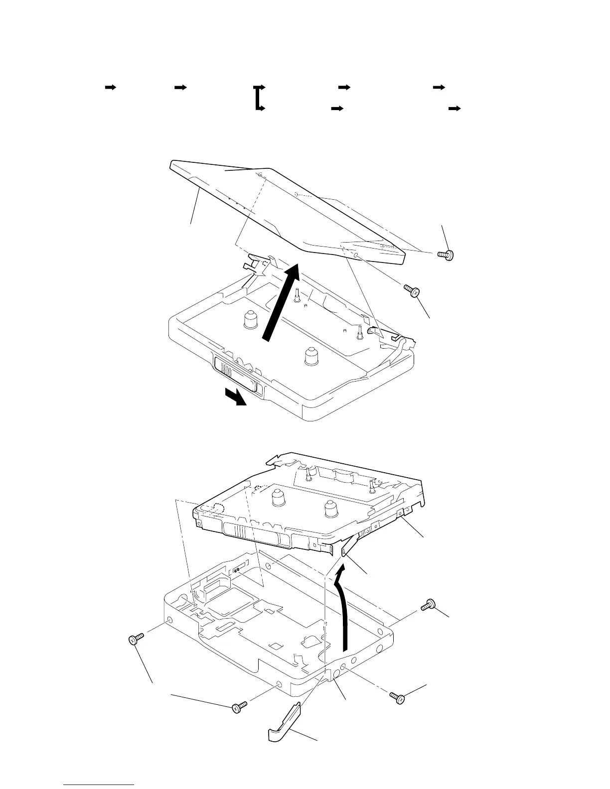
3-1. LID BLOCK ASSY, CASSETTE
3-2. CASE BLOCK ASSY
3
4
1 Two screws (1.4)
2 Screw (1.4)
Lid block assy, cassette
Mechanism deck block
3 Two screws (1.4)
4 Screw (1.4)
5
2 Two screws (1.4)
Case block assy
1 Lid, battery case
Claw
Lid Block Assy,
Cassette
Case Block Assy
Ornament (OPEN)
Block Assy
"Switch, Leaf (S704)"
Main Board
Belt (F0), Motor (M601)Set
Holder (FA) Assy Pinch Lever (NF)/(RF) Assy Head, Magnetic (HP701)