EasyManua.ls Logo

Sony WM-EX921 Service Manual

Sony WM-EX921
30 pages
To Next Page IconTo Next Page
Page #1 background imageLoading...
Page #1 background image
SERVICE MANUAL
Frequency response (Dolby NR off)
Playback: 30 - 18 000 Hz
Output
Headphones (i jack)
Load impedance 8 - 300
Power requirements
1.5 V
One rechargeable battery
Dimensions (w/h/d)
Approx. 77.1 × 108.8 × 20.2 mm
Mass
Approx. 147 g
Supplied accessories
Stereo headphones or earphones with remote control (1)
Battery charging stand (1)
AC power adaptor (1)
Rechargeable battery (NH-14WM (A), 1.2 V, 1 350 mAh
(MIN), Ni-MH) (1)
Rechargeable battery carrying case (1)
Carrying pouch (1)
Design and specifications subject to change without notice.
Battery life (Approx. hours) (in playback) (JEITA*)
Rechargeable NH-14WM (A) 45
fully charged
* Measured value by the standard of JEITA (Japan Electronics
and Information Technology Industries Association). (Using a
Sony HF series cassette tape)
Note
The battery life may be shorter depending on the
operating condition and the surrounding
temperature.
Ver 1.0 2001.10
9-873-307-01 Sony Corporation
2001J0500-1 Personal Audio Company
C 2001.10 Published by Sony Engineering Corporation
CASSETTE PLAYER
AEP Model
E Model
Chinese Model
Tourist Model
SPECIFICATIONS
WM-EX921
Manufactured under license from Dolby Laborato-
ries.
“Dolby” and the double-D symbol are trademarks of
Dolby Laboratories.
Model Name Using Similar Mechanism NEW
Tape Transport Mechanism Type MT-WMEX921-162
Question and Answer IconNeed help?

Do you have a question about the Sony WM-EX921 and is the answer not in the manual?

Sony WM-EX921 Specifications

General IconGeneral
BrandSony
ModelWM-EX921
CategoryCassette Player
LanguageEnglish

Summary

SECTION 1 SERVICING NOTES

Setting

Procedure for setting up the unit for voltage checks and operation.

Preset state

Steps to set the unit to PLAY, FF, REW modes.

SECTION 2 GENERAL

Preparations

Instructions for preparing the unit, including battery charging.

Playing a Tape

Guide to inserting a cassette and operating playback controls.

SECTION 3 DISASSEMBLY

3-1. DISASSEMBLY FLOW

Overview of the unit's disassembly sequence.

3-2. CASE SECTION

Steps to disassemble the case section of the unit.

3-3. MAIN BOARD

Instructions for removing the main board.

SECTION 4 MECHANICAL ADJUSTMENTS

SECTION 5 ELECTRICAL ADJUSTMENTS

SECTION 6 DIAGRAMS

6-3. PRINTED WIRING BOARD - MAIN Board (Component Side)

Component layout on the main board's component side.

6-4. PRINTED WIRING BOARD - MAIN Board (Conductor Side)

Component layout on the main board's conductor side.

6-5. SCHEMATIC DIAGRAM - MAIN Board (1/2)

First part of the main board schematic diagram.

6-6. SCHEMATIC DIAGRAM - MAIN Board (2/2)

Second part of the main board schematic diagram.

6-7. IC PIN FUNCTION DESCRIPTION

Detailed pin descriptions for system controller ICs.
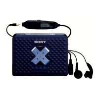
Related product manuals