6
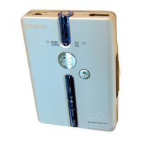
WM-EX921
SECTION 3
DISASSEMBLY
• This set can be disassembled in the order shown below.
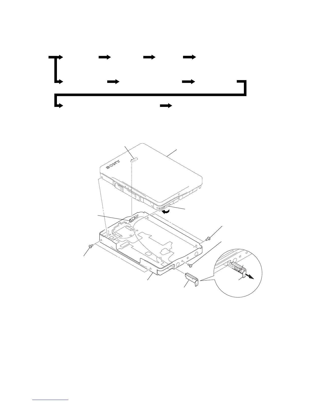
3-1. DISASSEMBLY FLOW
Note: Follow the disassembly procedure in the numerical order given.
3-2. CASE SECTION
3-9. “Lever (N2) Assy, Pinch”, “Lever (R2) Assy, Pinch”
Set 3-2. Case Section 3-3. Main Board
3-8. Holder (FA) Assy
3-10. Head, Magnetic (Playback) (HP901)
3-4. Belt (F0) 3-5. Motor, DC (Capstan/Reel) (M601)
3-7. Ornament (Open) Block Assy3-6. Lid Assy, Cassette
4
Close terminal board assy.
5
two screws
(M1.4)
6
screw (M1.4)
2
claw
1
Open “lid, battery
case”.
3
lid, battery case
7
case section
5
two screws
(M1.4)
knob (VOL)
S301
cassette assy, lid
Note: On installation
“lid assy, cassette” adjust
the S301 and knob (vol).