Cabinet (front) assySet Main board
Holder (sub) assy, cassette
Belt and MotorMechanism deckDisplay board
SECTION 2
DISASSEMBLY
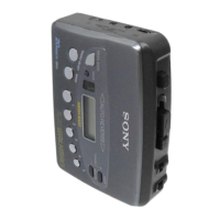
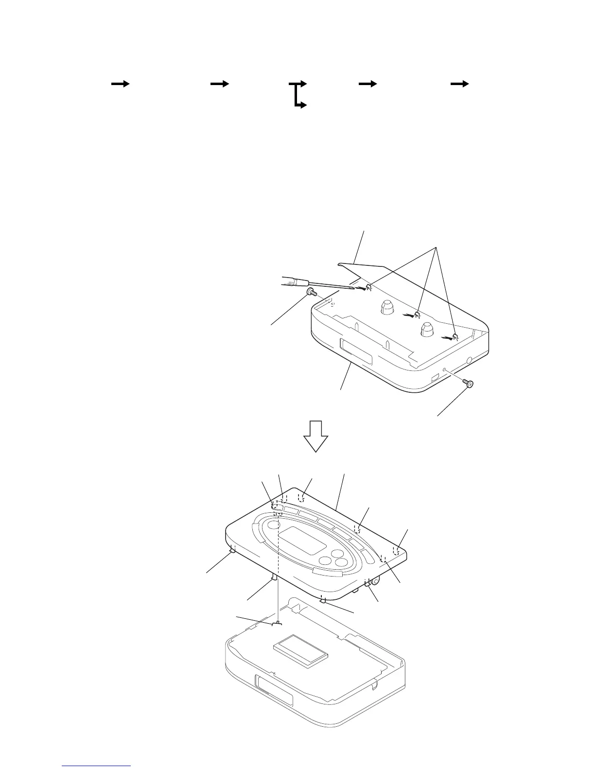
2-1. CABINET (FRONT) ASSY
Note : When installing, fit the knobs and switches.
3
Insert the precision screwdriver
(1.4 mm flat-blade) into the slit
at claw
A
and release the claw.
4
Remove the cabinet (front) assy.
(Release all claws
B
to
K
in
alphabetical order.)
• The equipment can be removed using the following procedure.
Note : Follow the disassembly procedure in the numerical order given.
Note :When removing the cabinet, put cloth
on the end of a screwdriver or use a
polyacetal driver to avoid damage to
the cabinet.

 Loading...