— 3 —
SECTION 1
GENERAL
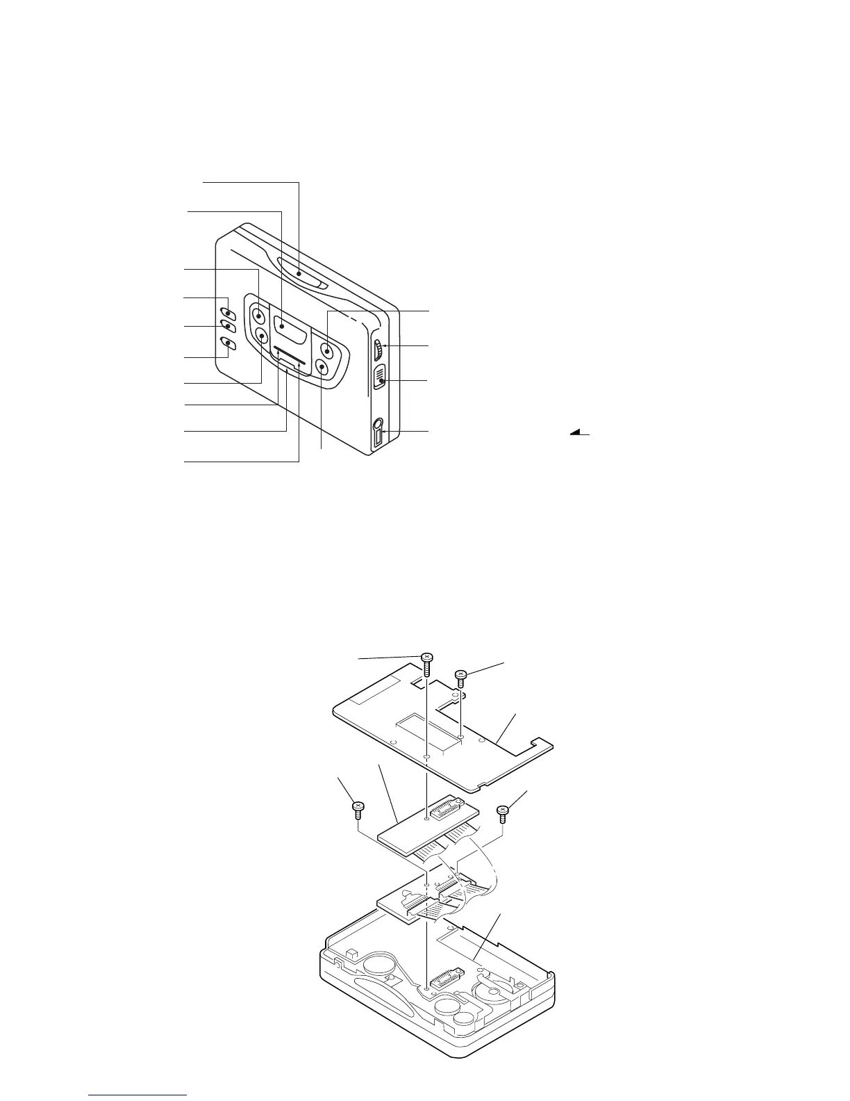
• LOCATION OF CONTROL
SECTION 2
SERVICE NOTE
• Regarding the method of adjustment and voltage check, perform sections 3-1 and 3-2 of the DISASSEMBLY, and attach the JIG (extension
cable) to the AUDIO board as shown below.
JIG Part No. : J-2503-005-A
Screw
(M1.4 × 5.0)
Screw (M1.4 × 5.0)
TUNER board
Screw (M1.7 × 4.0)
Screw
(M1.4 × 5.0)
JIG
AUDIO board
1
!¢
2
4
5
6
3
9
!
0
8
!£
!“
!`
7
1 OPEN knob
4 TUNING + button
6 ENTER button
7 ˇ /REPEAT button
8 p /RADIO OFF button
9 MENU button
0 SET button
! BAND button
!` VOLUME knob
!“ HOLD knob
!¢ Display window
!£
2 REMOTE jack
5 TUNING – button
2 PRESET + /AMS FF button
3 PRESET – /AMS REW button

 Loading...