12
Sookook Corporation
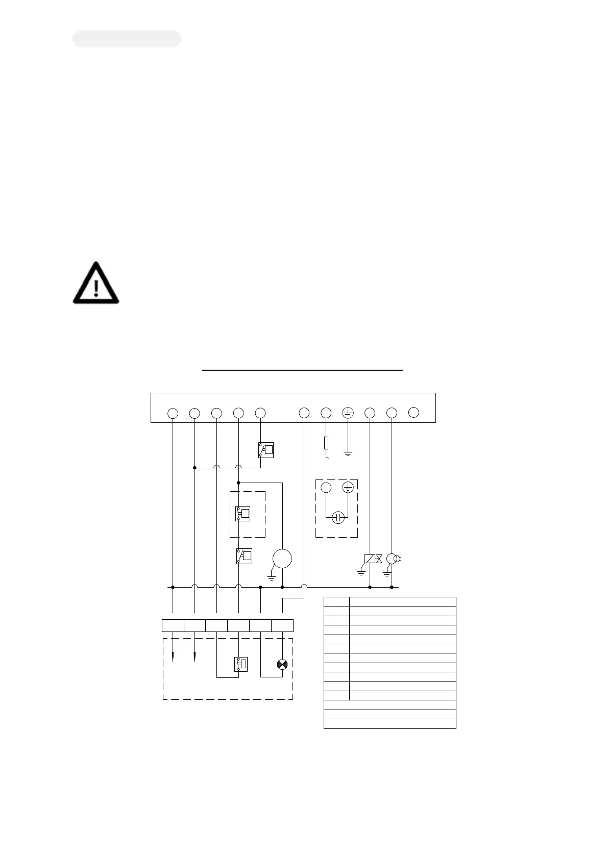
1H. Burner Circuit Diagram
Circuit Connection
If you open the burner control panel lid, you can see the burner power connection terminal and external interlock connection terminal
(MA) to connect the burner power and control circuits. The motive power supply for the motor connection and power supply for burner
control shall be independent. Both shall be connected to the burner via a fuse (NFB).
The HIGH / LOW control limit switch must be installed to automatically operate the HIGH / LOW operation. If it is not installed, the HIGH
/ LOW terminal must be forcibly connected. In this case, it is ON / OFF operation.
This is a standard circuit diagram for reference. (All burners have their own detailed circuit diagram.)
[Figure 1H-A. ON-OFF Circuit Diagram]
TA Ignition Transformer
PGSL Gas Pressure Low S/W
ST Load Limit S/W
PR Burner Controller
*1. Field Wiring
*2. In Case of UV Detector
*3. High Gas Pressure (P > 350mmAq)
FD Flame Detector
PAS Air Pressure S/W
MA External Connection Block
LB Burner LOCK-OUT Lamp
MV Fan Motor
EV Gas Solenoid V/V
(GAS BURNER MAXI ON-OFF TYPE)
WIRING CIRCUIT DIAGRAM (220V, 1Ø)
MA
3
FD
2 7
1Ø , 220V
LB
98
MV
EV
PGSL
TA
ST
P
N
4321
PAS
P
P R (MF2 RENEW)
5
10
1
P
4
6
N
8
PGSH
P
*3
50/60Hz
8
FD
+-
*2
9
*1
RedBluePurpleWhiteYellowBlue
T
PGSH Gas Pressure High S/W
Warnings
1. Before connecting the motive power to the burner, ensure that the supply voltage is the same as the voltage on the
burner name plate
2. Correctly connect the power phase and ground phase. (In the case of reverse wiring, there is a risk of explosion
due to short circuit upon the burner start-up.)
3. The burner's ground terminal shall be securely connected to the actual ground .
4. If HIGH / LOW control is required, the H / L thermostat (AB) must be connected to terminals 6 and 7. .