26
Sookook Corporation
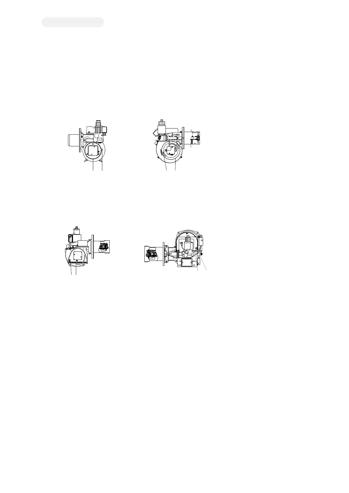
2G. Combustion Air Flow Control
Air Damper
An air damper is installed near the inlet to properly inflow the combustion air suitable for consumption during load operation, and it works in
conjunction with a damper motor and a linkage device.
ON/OFF BURNER
MAXI 5, MAXI 20S
Note
1 – Bolt/Nut for Air Damper
2 – Air Damper Cover
[Figure 2G-A. MAXI 5] [Figure 2G-B. MAXI 20S]
After loosening the bolt or nut for fixing the air damper, hold the air damper cover by hand and turn it to increase or decrease the opening
degree of the air damper. When the opening degree of the air damper increases, air flow increases, and when the opening degree of the air
damper decreases, air flow decreases. After adjusting the damper, tighten bolt and nut.
MAXI 8, 10, 16. 20, 25
Note
1 – Air damper Bolt
2 – Air damper Plate
[Figure 2G-C. MAXI 8 - 16] [Figure 2G-D. MAXI 20 - 25]
When the bolt for adjusting the air damper is turned clockwise, the opening degree of the air damper & air flow will increase, and when it is
turned counter clockwise, the opening amount of the air damper & air flow will decrease.
HIGH/LOW Burner(MAXI 32S(AB), MAXI 32)
Air flow control at low combustion mode
If you slightly loosen the bolt fixing the air damper shaft, you can turn the damper plate (2) with your hand, Hold the linkage device with one
hand and hold the damper plate with the other hand, move the damper to the angle with proper air flow and tighten the bolt again. (Turn
clockwise seen from behind the burner to increase the air flow and counter clockwise to decrease the air flow.)
You can also adjust the air flow by changing the angle of the low combustion positioning cam (cam II, See Figure 2C-A) in the damper motor.
It is recommended to check gas flow when controlling air damper because air damper shaft and gas butterfly valve is connected through the
linkage device.
Air flow control at high combustion mode
Air flow at high combustion mode shall be adjusted by angle of the high combustion positioning cam (cam I, See Figure 2C-A) in the damper
motor. At this time, the gas flow is changed as well. To adjust the gas flow, adjust the gas flow control device V1 of the gas solenoid valve
(See 2F, gas flow control).
2
1
5
6
4
8
7
1
3
2
0
21
21
MVDLE207/5
SW50A4
2
0
25
3
0
3
5
1
5
m
b
a
r
4
5
40
5
0
10
1
2