30
Sookook Corporation
3C. Combustion Head Inspection and Replacement
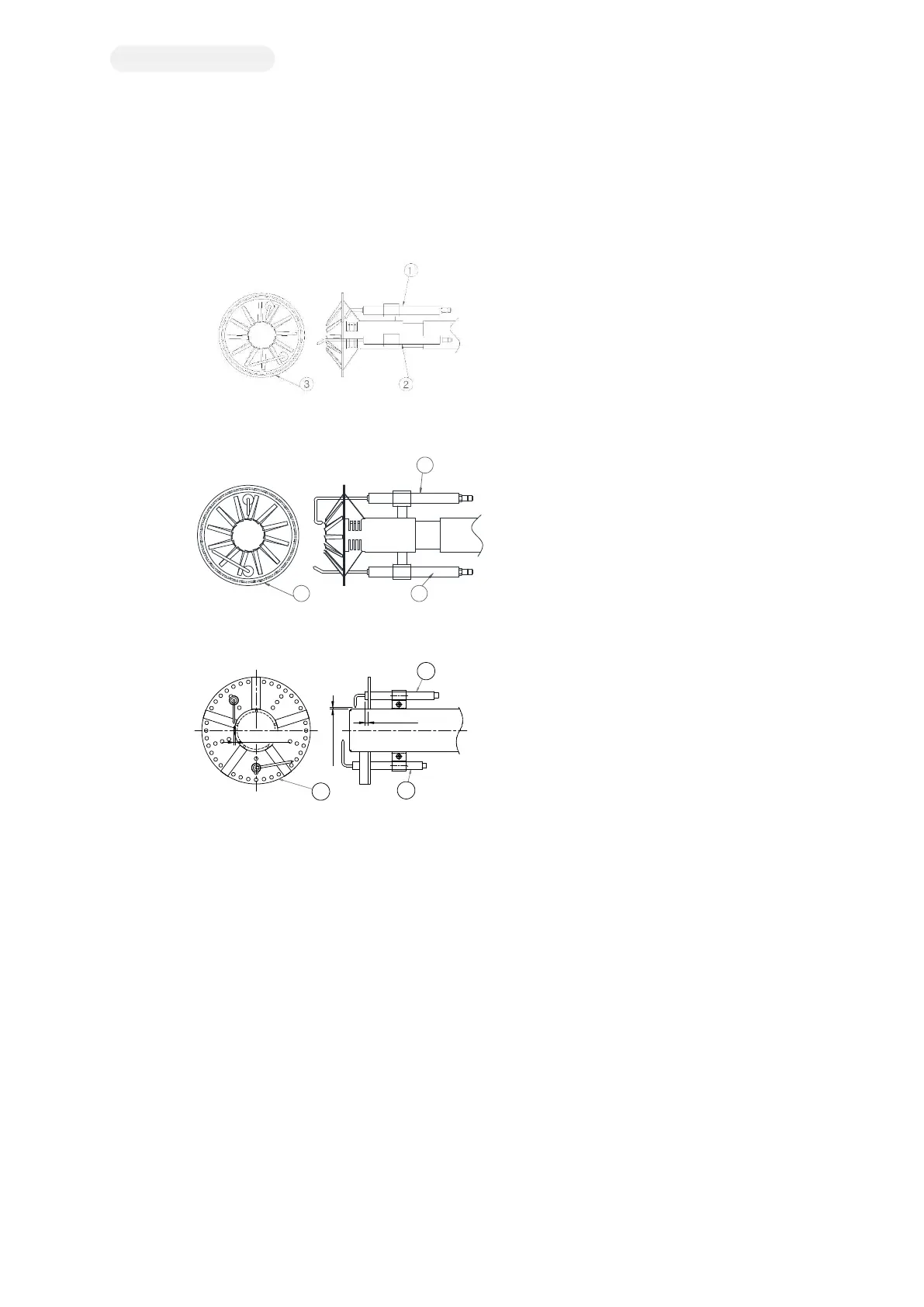
Positioning Method of Ignition Electrode
- Do not connect the cable of the ignition electrode and flame rod interchangeably.
- Keep the electrode well in the center to prevent metal parts from touching.
- Electric arc discharge shall be generated between high voltage electrode and ground electrode core.
Note
1- high voltage electrode
2- flame rod
3- Diffuser
[Figure 2H-A. MAXI 5, 8, 10, 16, 20S]
Note
1- high voltage electrode
2- flame rod
3- Diffuser
[Figure 2H-B. MAXI 20, 25, 32S]
Note
1- high voltage electrode
2- flame rod
3- Diffuser
[Figure 2H-C. MAXI Low NOx Burner, 32(LX)]
Adjust flame detection current
For MAXI type, since the flame detector is installed to the location where the flame detection signal output is at its maximum, there is no
need to adjust it separately.
If it is detected as necessary, it shall not be less than 20μA measured by a microampere meter capable of measuring 0-100μA current.
1
23
3
2
1
1.5~2 mm
1.5~2mm
5~8mm