**
INSTALLATION
BSS-134
CHAP.- 6
The power and compressed air supply cables should be brought close to the machine
with appropriate sheaths or channels, not to cause any obstacle for the operators and
to properly protect them at the same time.
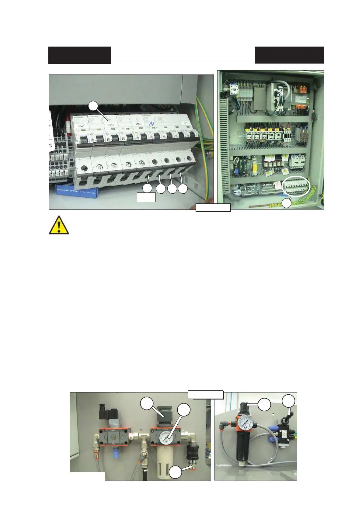
6.4 Connection to the compressed air system
Make the connection of the compressed air system [B] (see fi g.3 chap.6) to the fi lter unit.
Check with the pressure gauge [C] (see fi g.3 chap.6) that the pressure is equal to 6,5 bar.
If pressure needs to be adjusted because it is lower or higher than 6,5 bar, move the knob [D] (see
fi g.3 chap.6) upwards and rotate it clockwise to increase or counterclockwise to decrease the pressure
in the machine’s pneumatic circuit.
It is important to periodically check the effi ciency of the fi lter.
A malfunctioning of this part is the cause for a probable damage of the electric valves and of the
pneumatic cylinders.
6.4.1 Tracks pressure adjustment
The pressure of dragging tracks must be about 3 bars. If it is lower or higher it is necessary to lift up
the knob [E] (see fi g.3 chap.6) and to rotate it clockwise or counter clockwise in order to increase or
decrease the pressure.
To display the real pressure, it is necessary to move the knob, [G] (see fi g.3 chap.6) the valve by hand
(after having adjusted the pressure it is necessary to move the valve and to check again).
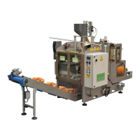
A
A
N
blue
R S T
Fig.2 chap.6
B
D
fi lter unit
C
E
Fig.3 chap.6
G