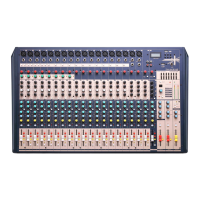
The following features are applicable to both M16 and M24. In case where different features need to be described for each model,
M16 will be described rst, followed by M24
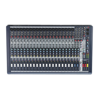
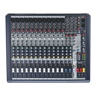
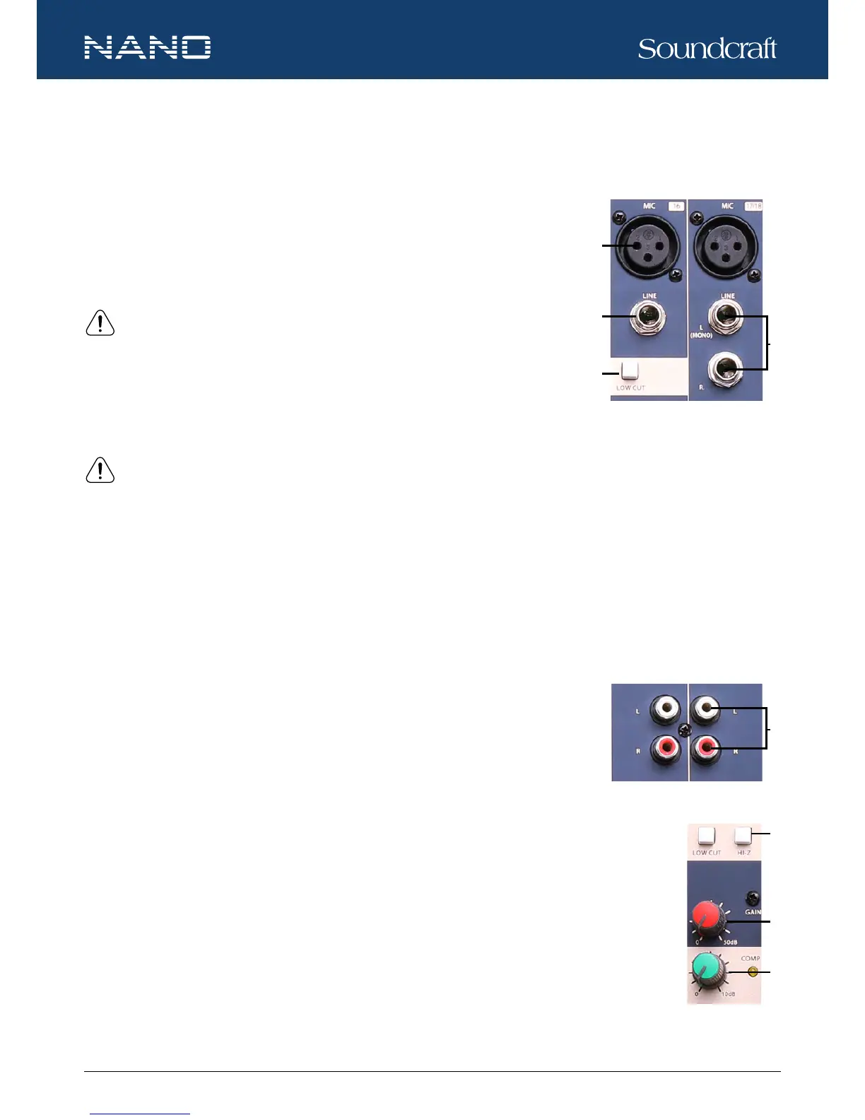
1. MIC INPUT JACKS (CH 1 to CH 11/12 for M16, CH 1 to CH 19/20 for M24)
These MIC input uses balanced XLR-type input jacks and are designed to accepts BAL-
ANCED or UNBALANCED signals. A +48V phantom power switch (at the rear panel) is
provided to power professional condenser mics.
NOTE: ONLY connect condenser microphones with the +48V phantom power
switched OFF, and ONLY switch on or off the +48V phantom power with all output
faders DOWN (∞), to prevent damage to the mixer or external devices.
2. LINE INPUT JACKS (CH 1 to CH 8 for M16, CH 1 to CH 16 for M24)
These LINE input use balanced TRS jacks and accept either BALANCED or UNBALANCED
signals.
NOTE: Unplug anything in the MIC input if you want to use this socket.
3. STEREO INPUT JACKS (CH 9/10 to CH 11/12 for M16, CH 17/18 to CH 19/20 for M24)
These L-R stereo input are organized in pairs of ¼” phone sockets. To connect a stereo device, plug both the left and right input
connectors. To connect a mono input signal, only use the left input, the output signal will appear on both sides.
4. LOW CUT
By pressing this button you will activate a 75Hz low frequency lter with a slope of 18dB per octave which reduces the hum noise
infected by the mains power supply or the stage rumble while using the microphone.
5. RCA INPUT JACKS (CH 13/14 to CH 15/16 for M16, CH 21/22 to CH 23/24 for M24)
These RCA input jacks are organized in stereo pairs. To connect a stereo device, plug both the
left and right input connectors.
6. HI-Z
Press the HI-Z switch will change the channel input to a high impedance input.
7. GAIN CONTROL
Adjusts the knob to set the input signal level. To achieve the best balance between S/N and dynamic range,
adjust the level so that the CLIP LED indicator light occasionally only on the highest input transients. For each
channel the MIC input adjustment range of the GAIN is 0-50dB and the sensitivity of line input is +20 to -30dB.
8. COMP CONTROL
Adjusts the amount compression applied to the channel. Turn the knob to the right to increase the com-
pression ratio and the output gain will automatically adjusted. The result is smoother, more even dynamics
because louder signals are attenuated which the overall level is boosted.
Controls and Features