-7-
2. Mainboard Power Switch Connection Cable
B1 : (2pin, iMON Inside ‘M/B PWR’
connector)
B2 : (2pin, Mainboard power switch
connector)
3. PC Case Power Switch Connection Cable
C1 : (2pin, iMON Inside ‘PWR S/W’
connector)
C2 : (2pin, PC Case power button connector)
4. Mainboard USB Connection Cable
D1 : (5pin, iMON Inside USB connector) D2 : (4pin, Mainboard USB internal connector)
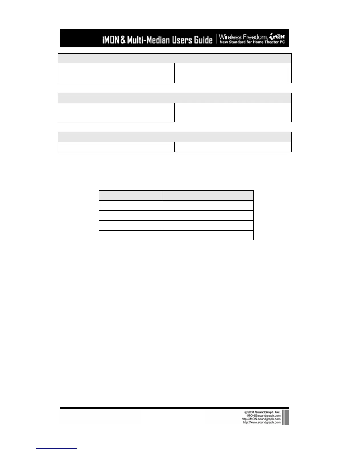
The names of the additional USB port pins on the mainboard manual are different with the
manufacturer. Please refer to the following table to connect the USB cable.
Line Color Additional USB Port Pin Name
RED VCC, POWER, USBPOWER
WHITE D-, DATA-, USBP#-, UP#-, P#-
GREEN D+, DATA+, USBP#+, UP#+, P#+
BALCK GND, GROUND
After all the connection finished, turn on your system. You may see the ‘Found New H/W
Wizard’ when Windows starts. Assign the CD ROM drive for searching H/W driver like the
external USB iMON station setup process.
3) Execute iMON Manager
After finish S/W and H/W installation, please execute the iMON Manager using the desktop
iMON icon. Please refer to the iMON Users Guide in order to learn about the various settings
and usage of iMON Manager.