Auto
Power
Off
MODE
RANGE
HOLD
REL
COM
10A
For
30sec.
MAX
every
15 min
FUSED
! !
9
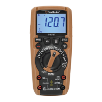
Operation
Resistance Measurements
1. Set the rotary function switch to
the Ω CAP position.
2. Press the MODE button until “MΩ”
appears on the LCD display.
3. Insert the black test lead into the negative
COM input jack. Insert the red test lead
into the positive Ω input jack.
4. Touch the test probe tips across the
circuit or component under test. It is
best to disconnect one side of the
device under test so the rest of the
circuit will not interfere with the
resistance reading.
5. Read the resistance on the LCD display.
Never test resistance on a live circuit.
WARNING:
Continuity Test
1. Set the rotary function switch to
the Ω CAP position.
2. Press the MODE button until “ ”
appears on the LCD display.
3. Insert the black test lead into the negative
COM input jack. Insert the red test lead
into the positive Ω input jack.
4. Touch the test probe tips to the circuit
or wire you wish to check.
5. If the resistance is approximately 30Ω
or less, an audible tone will sound. If
the circuit is above 400Ω, the LCD
display will indicate “OL”. The resistance
will be shown on the display if it is
below 400Ω.
Never test continuity on a live circuit.
WARNING:
Ohms
Auto
Power
Off
MODE
RANGE
HOLD
REL
COM
10A
For
30sec.
MAX
every
15 min
FUSED
! !
WIRE
CAT III 600V
CAT III 600V
10
Red
Probe
FORWARD TEST REVERSE TEST
Red
Probe
Black
Probe
Black
Probe
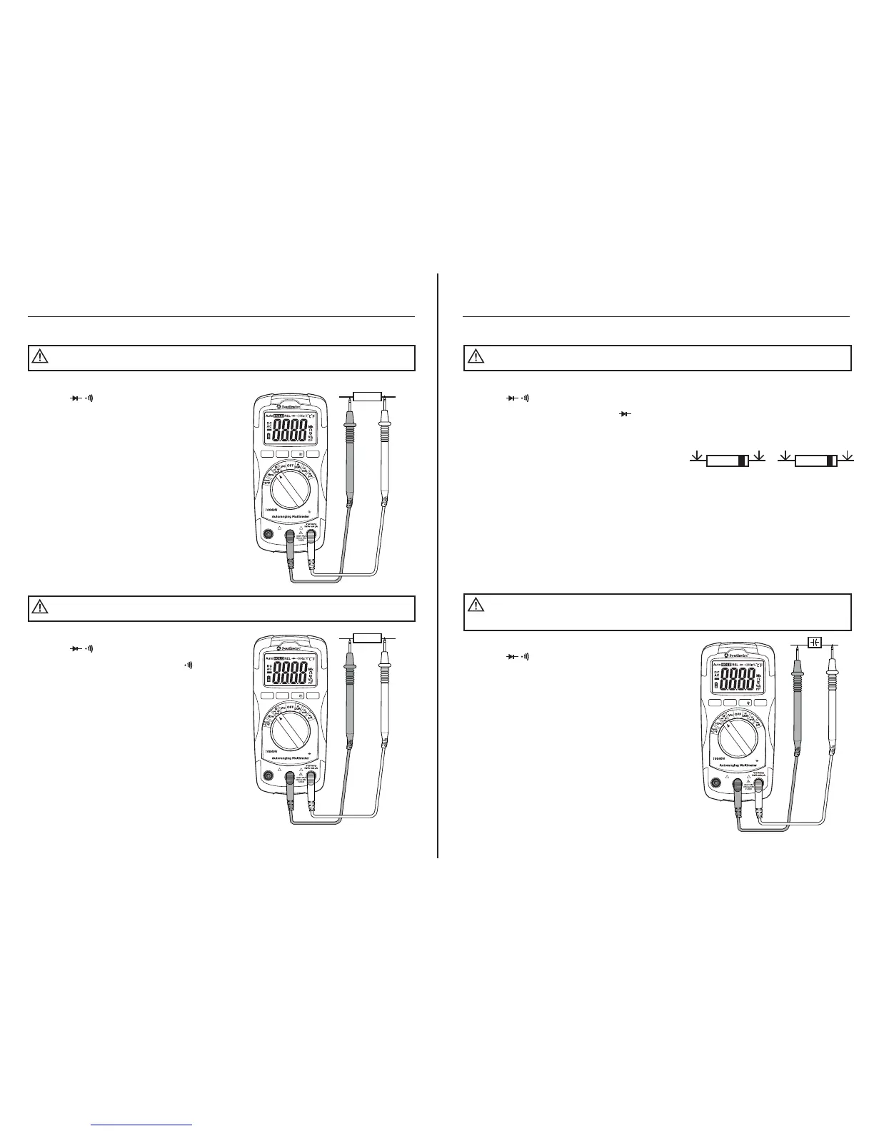
Operation
Diode Test
1. Set the rotary function switch to
the Ω CAP position.
2. Press the MODE button until “ ”
appears on the LCD display.
3. Insert the black test lead into the negative
COM input jack. Insert the red test lead
into the positive Ω input jack.
4. Touch the test probes to the diode under
test. Forward voltage will indicate 0.4 to
0.7V. Reverse voltage will indicate “OL”.
Shorted devices will indicate near 0mV
and an open device will indicate “OL” in
both polarities.
Never test diodes in a live circuit.
WARNING:
Capacitance Measurements
1. Set the rotary function switch to
the Ω CAP position.
2. Press the MODE button until “nF”
appears on the LCD display.
3. Insert the black test lead into the negative
COM input jack. Insert the red test lead
into the positive Ω input jack.
4. Touch the test leads to the capacitor
to be tested.
5. Read the capacitance value on the LCD
display. The meter will automatically
adjust ranges between nF and µF. Large
capacitors may take up to a minute to
get a stable reading.
Safely discharge capacitors before taking capacitance
measurements.
WARNING:
Auto
Power
Off
MODE
RANGE
HOLD
REL
COM
10A
For
30sec.
MAX
every
15 min
FUSED
! !
CAT III 600V

 Loading...