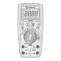
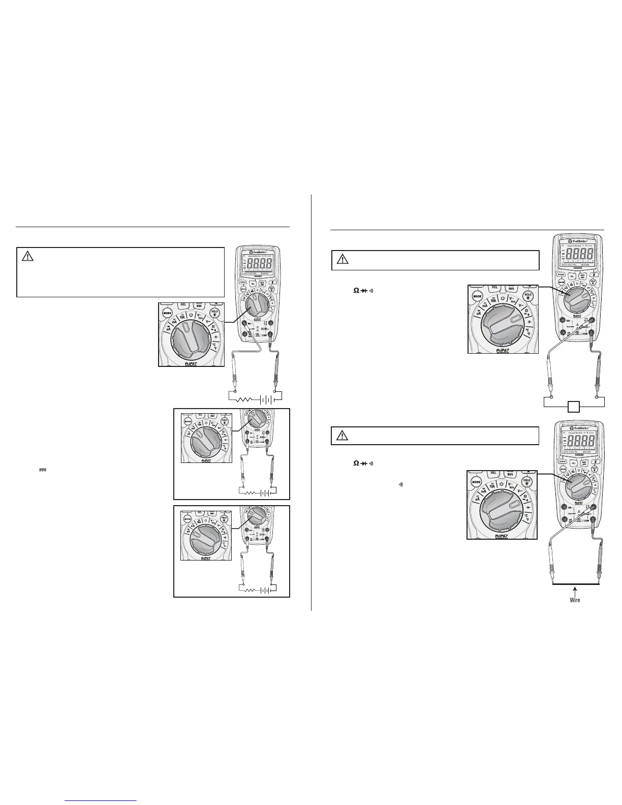
1. Insert the black test lead into the
negative COM input jack.
2. For current measurements up to 10A,
set the rotary function switch to the
10A position and insert the red test
lead into the 10A input jack.
3. For current measurements up to
600mA, set the rotary function switch
to the mA position and insert the red
test lead into the µA mA input jack.
4. For current measurements up to 6000 µA,
set the rotary function switch to the µA
position and insert the red test lead into
the µA mA input jack.
5. Momentarily press the MODE button to
select AC or DC current. The AC “~” or
DC “ ” symbol will appear on the LCD
display.
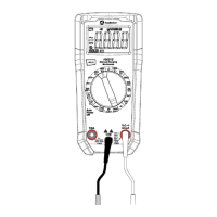
6. Remove power from the circuit under test,
then open up the circuit at the point where
you wish to measure current.
7. Touch the test lead probes in series with
the circuit being measured. For DC current,
touch the red probe to the positive side of
the circuit and touch the black probe to
the negative side of the circuit.
8. Apply power to the circuit.
9. Read the current on the LCD display.
AC/DC Current Measurements
MEASUREMENTS
UP TO 10A
Observe all safety precautions when
working on live circuits. Do not measure current on circuits
that exceed 1000V. Measurements in the 10A range should
be limited to 30 seconds maximum every 15 minutes.
WARNING:
MEASUREMENTS
UP TO 6000 µA
-+
12
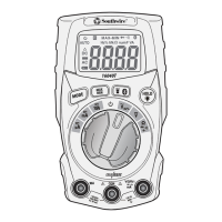
Operation cont.
1. Set the rotary function switch to
the position.
2. Momentarily press the MODE
button until the “ ” symbol
appears on the display.
3. Insert the black test lead into
the COM input jack and the red
test lead into the Ω input jack.
4. Touch the test lead probes to
the device or wire under test.
5. A beeper will sound if the resistance is approximately
30Ω or less and the resistance value will be shown
on the LCD display.
Continuity
Never test continuity on a live circuit.
WARNING:
Ω
1. Set the rotary function switch to
the position
2. Press the MODE button until the
“Ω” symbol appears on the LCD
display.
3. Insert the black test lead into the
COM input jack and the red test
lead into the Ω input jack.
4. Touch the test lead probes to the
component under test. If the component is installed
in a circuit, it is best to disconnect one side before
testing to eliminate interference with other devices.
5. Read the resistance in on the LCD display.
Resistance Measurements
Never test resistance on a live circuit.
WARNING:
 Loading...