5 6
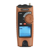
Symbols Used on LCD Display cont. Operation
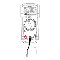
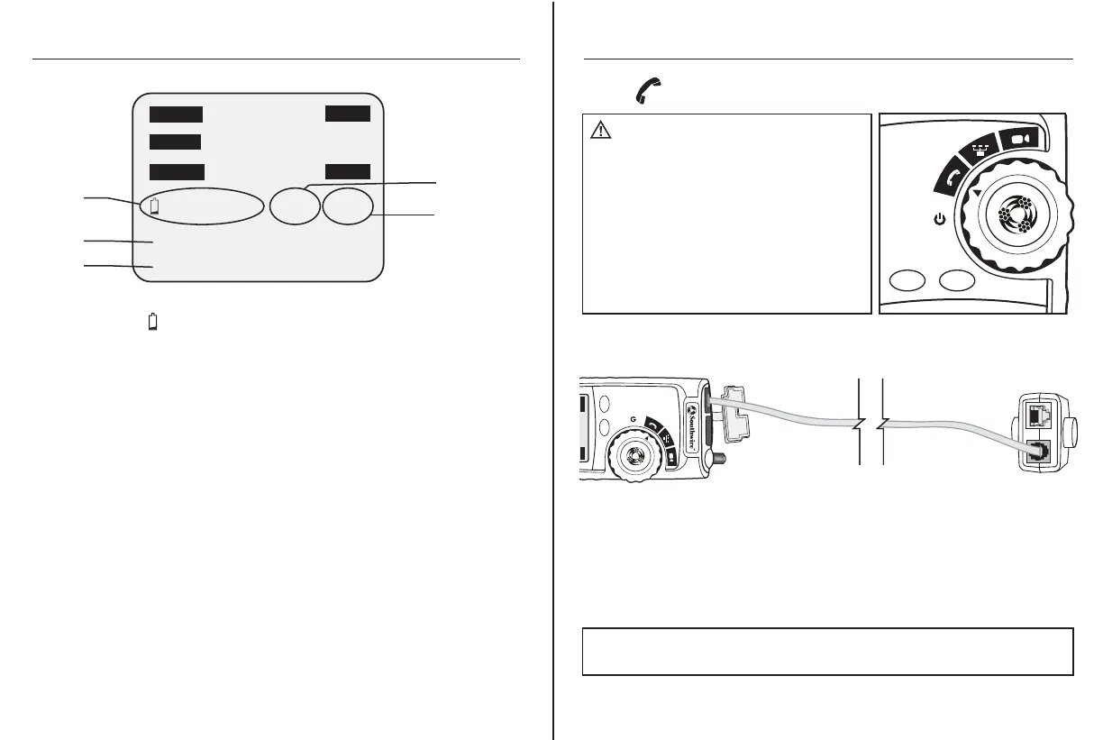
1. Connect one end the cable under test to the RJ11/RJ12 port on the tester.
2. Detach the remote from the bottom of the tester.
3. Connect the other end of the cable under test to the RJ11/RJ12 port
on the remote.
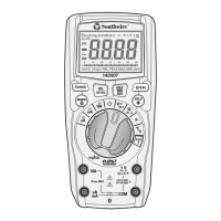
4. Set the rotary function switch to the Voice position.
5. Interpret the results using the Wiring and Display Examples on page 9.
Voice
WARNING: Exposure to voltage can
damage the tester. Immediately disconnect the
cable under test if the Voltage warning appears
on the display. Make sure the cable is not
connected to any device that can supply voltage
before retesting.
Do not connect two different cables into the
Voice (RJ11/12) and Data (RJ45) test ports
at the same time. The cables will interact with
each other and alter test results.
M300P
CYCLE
MODE
M300P
CYCLE
MODE
Open
Rev
Shield
Split ID 1
Test
Short
Tone
Data
Voice
Video
12345678
Detachable
Remote
6.
12345678
Open
FailPass
Rev
Shield
Volt! X-over Split ID 1
Test
Short
Tone
Data
Voice
Video
9.
12345678
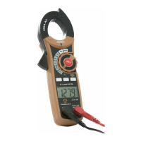
6. Low Battery : Indicates low battery. When this symbol appears,
results from the tester may not be reliable and the battery should
be replaced immediately.
Volt!: Flashes when the tester is connected to a cable with voltage
on it. Exposure to voltage can damage the tester. If this warning
appears, immediately disconnect the cable from the tester.
X-0ver: Appears when the tester detects a properly wired cross
over cable.
7. Split : Appears when the tester detects the signal is split
between two or more pairs.
8. ID 1: Appears when the tester detects a Remote ID. The number
that appears corresponds to the number on the Remote ID.
9. Wire Map near end: The top row of numbers displays the
connector pins on the tester end of the cable in numerical order.
These pins are mapped to the pins shown directly below on the
bottom row of numbers.
10. Wire Map remote end: The bottom row of numbers displays
the corresponding pin numbers on the remote end of the cable.
Dash lines indicate shorted pins. No pin numbers indicate an
open pair.
10.
7.
8.
NOTE: Split may appear on the display when testing cables that have
no twisting on the pairs.