SOYAL
ACCESS CONTROL SYSTEM
®
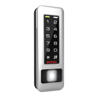
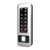
AR-321 (H) / AR-331 (H) /
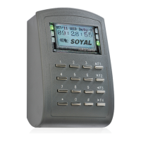
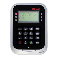
AR-721(H) / AR-725 (H) / AR-757 (H)
V140707
AR-321H
P4
P6
P1
P2
P3
P4
P5
P1
P2
P3
P4
P5
P1
P2
P3
P4
P5
P1
P2
P3
P1
P2
P3
P4
P5
P1
P2
P3
P4
P5
125kHz
125kHz
125kHz
125kHz
13.56MHz
13.56MHz
13.56MHz
13.56MHz
P7
LED
LED
10 98765432
P4
P6
P1
P2
P3
125kHz 13.56MHz
P1Cable :
P2Cable :
P3Cable :
P4Cable :
(Contact Rating: 1A 125VAC/24VDC)
P5Cable :
(Optional)
P6Cable :
P7Cable :
(Directly connected at the Access controller)
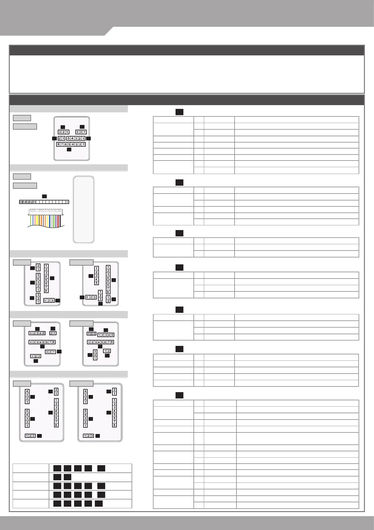
Wire Application
Wiegand
Beeper
Wiegand
Pin
1
2
3
4
5
Color
Thin Blue
Thin Green
Pink
Brown
Yellow
Description
Wiegand DAT:1 Input
Wiegand DAT:0 Input
Beeper Output 5V/100mA, Low
LED Green Output 5V/20mA, Max
LED Red Output 5V/20mA, Max
Wire Application
Networking
Module
Pin
1
2
Color
Thick Green
Thick Blue
Description
RS-485(B-)
RS-485(A+)
※
After S/N: 0706-XXXXXX
Wire Application
Tamper Switch
Pin
1
2
3
Color
Red
Orange
Yellow
Description
N.C.
COM
N.O.
Wire Application
3-PIN Connector
Pin
1
2
3
Color
Black
White
Purple
Description
GND.
Duress
Arming/ Security trigger signal
Wire Application
Doorbell
Arming
Duress
LED indicator
Pin
1
2
3
4
Color
Brown White
Red White
Yellow White
Green White
Description
BE Output
AR Output/ Security trigger signal Output
DU Output/ TTL out
Hi input/ Green light brighten
AR-321 (H)
AR-721 (H)
AR-331 (H) / AR-331 (H-S)
AR-725 (H)
AR-757 (H)
Wire Application
Lock Relay
Common-COM-Point
Door contact
Exit Switch
Alarm Relay
Power
Wire Application
Exit Switch
Networking Module
Networking Module
Alarm Relay
Door contact
Beeper
Tamper Switch
Lock Relay
Power
Pin
1
2
3
4
5
6
7
8
Pin
1
2
3
4
6
7
8
9
10
11
12
13
14
15
5
Color
Blue White
Purple White
White
Orange
Purple
Gray
Thick Red
Thick Black
Color
Thick Black
Thick Red
Purple
Thick Green
Thick Blue
Yellow White
Orange White
Gray
Orange
Brown
Yellow
Pink
Thin Blue
Thin Green
Description
(N.O.) DC24V1Amp
(N.C.) DC24V1Amp
(COM) DC24V1Amp
Negative Trigger Input
Negative Trigger Input
Low output; Max 12V/100mA (Open Collector)
DC Power 12V
DC Power 0V
Description
DC Power 0V
DC Power 12V
Negative Trigger Input
RS-485(B-)
Low output; Max 12V/100mA (Open Collector)/
Security trigger signal Output
RS-485(A+)
N.O.
COM
Low output; Max 12V/100mA (Open Collector)
Negative Trigger Input
LED Green Negative Output 5V/20mA, Max
LED Red Negative Output 5V/20mA, Max
Beeper Negative Output 5V/100mA, Low
Wiegand DAT:1 Input
Wiegand DAT:0 Input
Connector Table
AR-321 (H)
AR-331 (H)
AR-721 (H)
AR-725 (H)
AR-757 (H)
Connectors Comparison
P1 P2 P3 P4 (
Optional
)P5
P7 P8
P1 P2 P3 P4 (
Optional
)P5
P1 P2 P3 P4 (
Optional
)P5
P1 P2 P3 P4 P6
Notice
The communication wires and power line should NOT be bound in the same conduit or tubing.
Don’t equip controller and lock with the same power supply. The power for controller may be unstable when the lock is activating, that may make
the controller malfunction.
The standard installation: Door relay and lock use the same power supply, and controller use independent power supply.
Use AWG 22-24 Shielded Twist Pair to avoid star wiring.
1.Tubing:
2.Wire selection:
3.Power supply:
White
 Loading...