Do you have a question about the Soyal AR-837 E and is the answer not in the manual?
Steps for mounting the unit to the wall using screws.
Steps for digging a hole and mounting the unit.
System auto-exits programming mode after 30 seconds of inactivity.
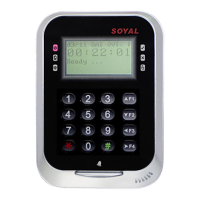
Explains the meaning of OK (green) and Error (red) LED lights.
Keypad locks for 30 seconds after incorrect PIN or master code entry.
Describes the meaning of Arming (green) and Alarm (red) status lights.
Shows wiring diagram for connecting an electric bolt lock.
Shows wiring diagram for connecting a magnetic lock.
Shows wiring diagram for connecting an electric strike.
Shows wiring diagram for connecting a door contact sensor.
Shows wiring diagram for connecting a reader and exit switch.
Wiring diagram for connecting door releases for fire emergency.
How to lock and unlock the device's keypad.
Steps to enter and exit the programming mode.
Procedure to change the master code for the system.
Covers language setting and reader node ID configuration.
Instructions for adding and deleting user tags (cards).
How to configure the access mode (card, PIN, etc.).
How to set or manage user PIN codes.
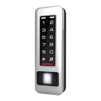
Instructions for adding and deleting fingerprint data.
Details different access modes (Invalid, Card, Card/PIN, Fingerprint).
How to set or change the arming password.
Setting the delay time for armed pulse output.
How to set and use the duress code for warnings.
Configuration options for terminal ports and baud selection.
How to set up alarm and arming conditions and situations.
How to configure access in standby mode (card only, card/PIN).
Configuration for anti-pass-back functionality.
Setup for controlling user access to specific floors.
Configuring single floor access for users.
Configuring multi-floor access for users.
Setting daily alarms or bell times.
Hardware installation diagram for the alarm/horn/music box.
Configuration for the auto-open zone feature.
Configuration for time zones for auto-opening doors.
Steps to run the UdpUpdater software for firmware.
How to reset device parameters and user data to factory defaults.
Procedure to reset the device's IP address using the RESET button.
How to access the device via its default IP address in a web browser.
Overview of the web browser page menu (Current Status, Network Setting, User Password).
How to monitor the online status and connected computers.
How to log in to the device's web interface using default credentials.
How to change the device's IP address and network settings.
How to change the password for the web interface login.
| Model | AR-837 E |
|---|---|
| Type | IP Access Controller |
| Power Supply | 12V DC |
| Event Log | Yes |
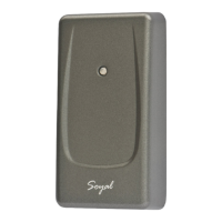
| Card Reader Interface | Wiegand |
| Door Relay Output | 1 |
| Alarm Relay Output | 1 |
| Operating Voltage | 12V DC |
| Communication Interface | RS-485, TCP/IP |
| Current Consumption | 200mA |
| Humidity | 10% to 90% (Non-condensing) |
| Weight | 200g |