The Servo Trigger was designed to make using servo motors easy, but it
may not fit every application. You might need different timing, or different
logic that interprets how the input is translated into the motor drive signal.
Since the heart of the Servo Trigger is a microcontroller, the firmware on
that controller can be reprogrammed. And because the design is released
as Open Source Hardware, the source code for the firmware is published in
the device’s GitHub Repository. You’re welcome to download and modify it!
Toolchain
The Servo Trigger firmware was developed in Atmel Studio 6.2.1153, using
a JTAGICE3 debugging module. The JTAGICE3 can configure and
program the chip, and also offers a full-featured interactive debugger. You
can pause execution and inspect the chip internals, which makes
troubleshooting the application significantly simpler – especially because
the Tiny84 lacks a serial port that could print debugging information.
If you’re using Atmel Studio, the
/firmware/ directory in the repo contains
the project and solution files.
While Atmel Studio makes a nice graphical front end and has a full-featured
debugger, it is not required to recompile the firmware or reprogram the IC.
You can use the command-line WinAVR tools, and program the board
using an AVR-Dude compatible programmer, like our Tiny AVR
Programmer. If you’re going this route,
Firmware\ServoTrigger\Debug
contains the WinAVR compatible makefile.
Firmware Modifications
Timing
The range of transit times accessed by the T potentiometer is defined by a
table of software values – the table interprets pot position using an
exponential curve, which allows for fine control of very short times on the
low end, but still premits a useful longer range at the top. But perhaps these
times don’t fit your application especially well – maybe you need extra
resolution at the low end, or much longer times at the top end. You can
change the timing table to do this.
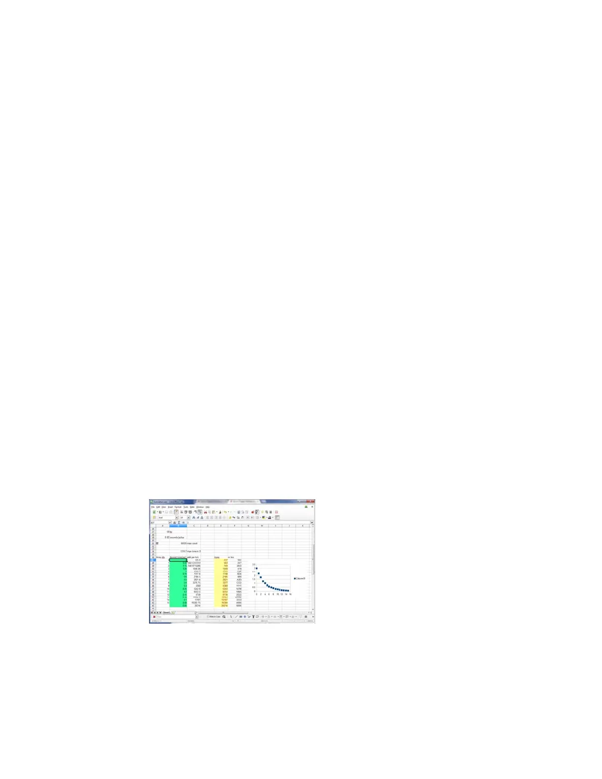
The table is calculated using the “translation.ods” spreadsheet. Simply type
the desired time in seconds into the green cells. The sheet recalculates the
timing values, and updates the yellow cells. Cut and paste the yellow cells
into the
timelut array.
The table is only 17 entries long, which seems rather short – but keep in
mind we’re using a microcontroller with only 8KB of flash memory and 512
Bytes of RAM – we wouldn’t want the timing table to fill the whole memory.
To increase resolution between the table entries, the firmware performs
linear interpolation to create more finely grained points in between.
Modes
Page 11 of 1
 Loading...