The table below summarizes common color schemes.
Pin
Number
Signal
Name
Color
Scheme
1
(Futaba)
Color
Scheme
2
(JR)
Color
Scheme
3
(Hitec)
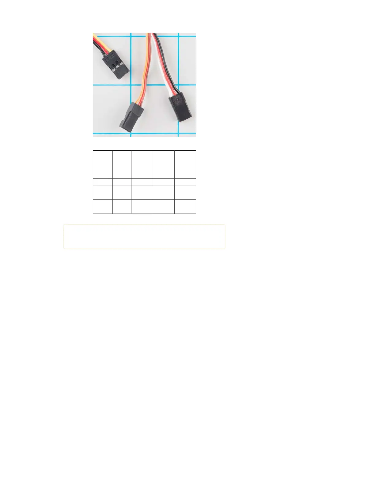
1 Ground Black Brown Black
2
Power
Supply
Red Red
Red or
Brown
3
Control
Signal
White Orange
Yellow or
White
Servo connection Color Coding
Heads up! If you’re in doubt about your color scheme, check the
documentation – don’t plug it in backwards!
Powering Servos
In RC vehicles, 5.5V is the nominal battery voltage. It will be somewhat
higher after a charge, and it will droop as the batteries discharge. As the
voltage drops, the available torque also drops – if you’ve driven RC
vehicles, you’re no doubt familiar with the loss of control that occurs as the
batteries get weaker. It starts to feel sluggish just before it dies.
If you’re not using batteries, the 5VDC available from a garden variety
power supply is a good option. If you’re using the Servo Trigger to control
your motor, the absolute maximum supply voltage that should be applied
is 5.5 VDC.
Regardless of how you’re powering them, it’s worth noting that the current
consumed by the motor increases as the mechanical loading increases. A
small servo with nothing attached to the shaft might draw 10 mA, while a
large one turning a heavy lever might draw an Ampere or more!
Control signal
Servos are controlled with a specific type of pulse train signal. The pulses
occur at a 20 mSec (50 Hz) interval, and vary between 1 and 2 mSec in
width. The Pulse Width Modulation hardware available on a microcontroller
is a great way to generate servo control signals.
Common servos rotate over a range of 90° as the pulses vary between 1
and 2 mSec – they should be at the center of their mechanical range when
the pulse is 1.5 mSec.
Page 3 of 1