Finally, apply power. The servo will probably jump to a new position as you
do this.
Then, press and hold the switch. The servo will rotate, taking a couple of
seconds to reach its new position. Release the switch, and it will go back to
the starting point.
Now you can adjust the trimpots to configure the servo.
•
A sets the position the servo sits in while the switch is open.
•
B sets the position the servo moves to when the switch is closed
•
T sets the time it takes to get from A to B and back.
Turning the position pots clockwise will make the motor turn further
clockwise. If A is higher than B, then the servo will turn counterclockwise
when the switch is actuated. The timing range is adjustable between 50
milliseconds and 3 seconds. The transit time is constant – when set to 2
seconds, the servo will take 2 seconds to move between A and B,
regardless of how close the position settings are.
In the next section, we’ll explore some of the finer details of the Servo
Trigger.
More Details
On The Board
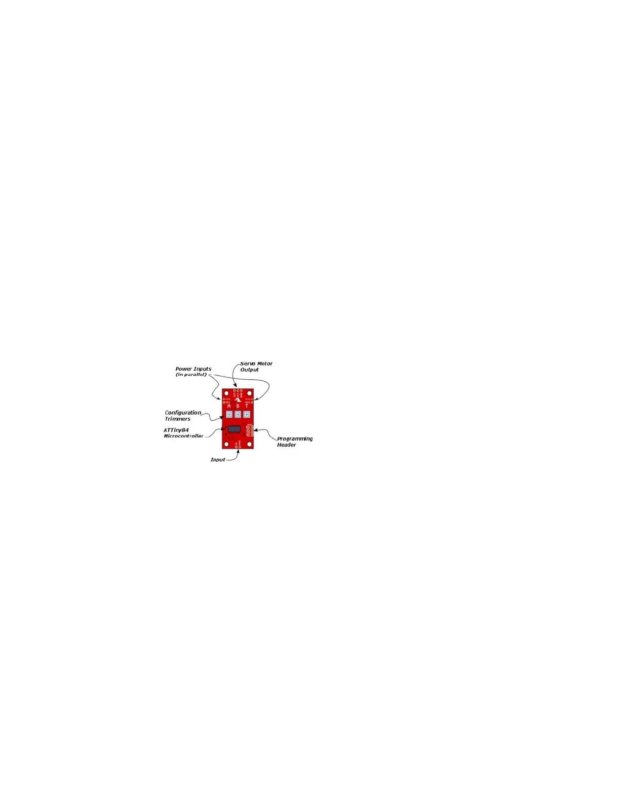
Let’s look at the components on the board and examine how it works.
The heart of the Servo Trigger is an Atmel ATTiny84 microcontroller,
running a small program that implements the servo control features we are
discussing here. Just because the Servo Trigger saves you from needing to
write code doesn’t mean that there’s no programming involved!
The servo control signal is generated using a 16-bit hardware timer. It runs
off a 1 MHz clock, counting to 20000 to generate the 20 mSec (50 Hz)
period and configured to generate pulses that range from 1000 to 2000
µSec (1 to 2 milliseconds).
The three potentiometers are connected as voltage dividers between VCC
and ground. They are read using analog inputs ADC0, ADC3, and ADC7.
The switch input is read using PortA, input pin 1. It is debounced in
software and can be configured to watch for a switch closure, or a logic
level pulse.
If you’re interested, you can download the schematic, PCB layout and
firmware files from the Servo Trigger GitHub Repository. The board also
includes the common 6-pin in-system-programming header, which we’ll
discuss in the Expert Exercises section. But we’re getting a bit ahead of
ourselves – there are configuration options you can use without
programming.
Page 7 of 1
 Loading...