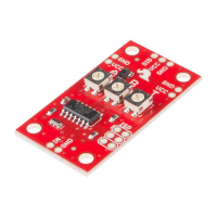
Switch Assembly
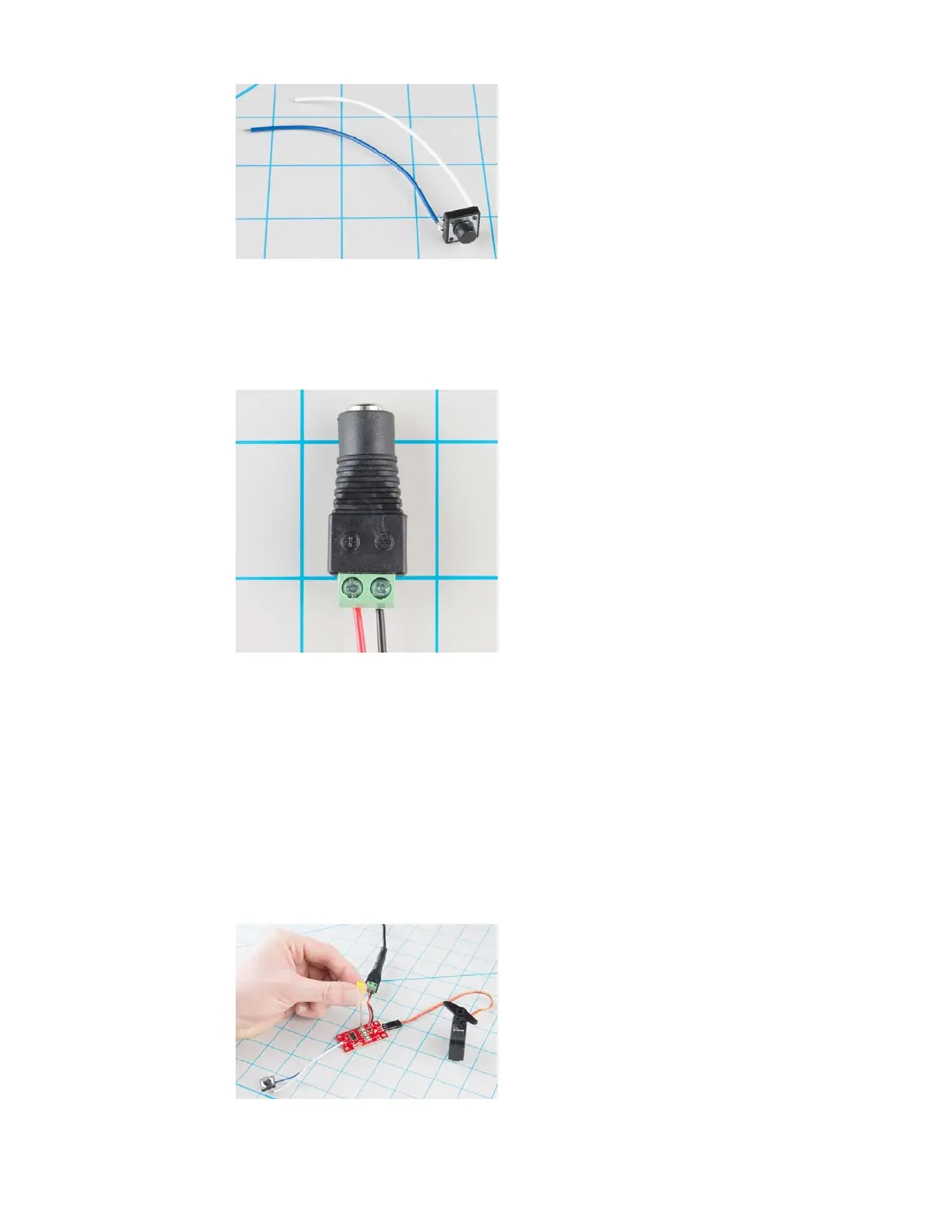
Then prepare the power plug pigtail. Take a pair of wires, and strip the
ends, then screw them to the power jack adapter – if you look closely at the
adaptor, you’ll notice that there are a small
+ and - embossed in the
plastic. We used a red wire for VCC on the
+ terminal, and a black wire for
ground on the
- terminal.
Power Jack Closeup
Next, solder the 3-pin header to the 3 pads on the end the board, and plug
the servo into the the header. Be careful to get the plug oriented correctly –
you can check the color code table in the previous section, or consult the
servo manufacturer’s datasheet.
Then solder the switch wires to the
IN and GND pads on the Servo
Trigger, and the power pigtail to the
VCC and GND pads on the edge of the
board. These are mirrored on opposite edges of the board – they’re wired in
parallel, so you can use either set of pads. The red wire should connect to
the
VCC pad, and the black to GND .
Before we power up, take a moment to double-check your work against the
photo below (click on the picture for a larger version). In particular, make
sure that the power and servo connections are oriented correctly.
Adjust the trimpots on the back of the board. Set A fully counterclockwise,
B fully clockwise, and set T to the middle.
Page 6 of 1