9
6. Operation
6.1 To Fill Pump with Oil
Fill crankcase with an SAE30 quality oil through opening above crosshead (23).
BS15 BS25 BS40 BS50
0,2 litres 0,3 litres 0,8 litres 1,0 litres
6.2 To Fill Pump with Water
Fill up pump head with water by pouring the water in via filler plug (33) At the same time, turn the pump
V-belt pulley (18) manually in the direction of the arrow. In the case of long suction lines, fill right up to the
foot valve/intermediate valve (see 5.4)
6.3 Motor Alignment and Electrical Connection
Using a ruler, make sure the pump pulley and motor V-belt pulley (18/18b) are in line with each other. The
motor could have been shifted during transport and if the pulleys do not align precisely, the belts will wear
out quickly.
Electric motors must be connected as per circuit diagram which can be found in the terminal box of the
electric motor. This work is to be carried out by suitably qualified persons.
6.4 Fittings
Open shut-off fittings and taps in the discharge line so that the air in the pipe system can escape.
6.5 To Switch on Motor
Check the direction of rotation. Reverse polarity if the motor is running in the wrong direction. Close the
shut-off fitting only after water has begun being pumped, after the suction line and pump are vented
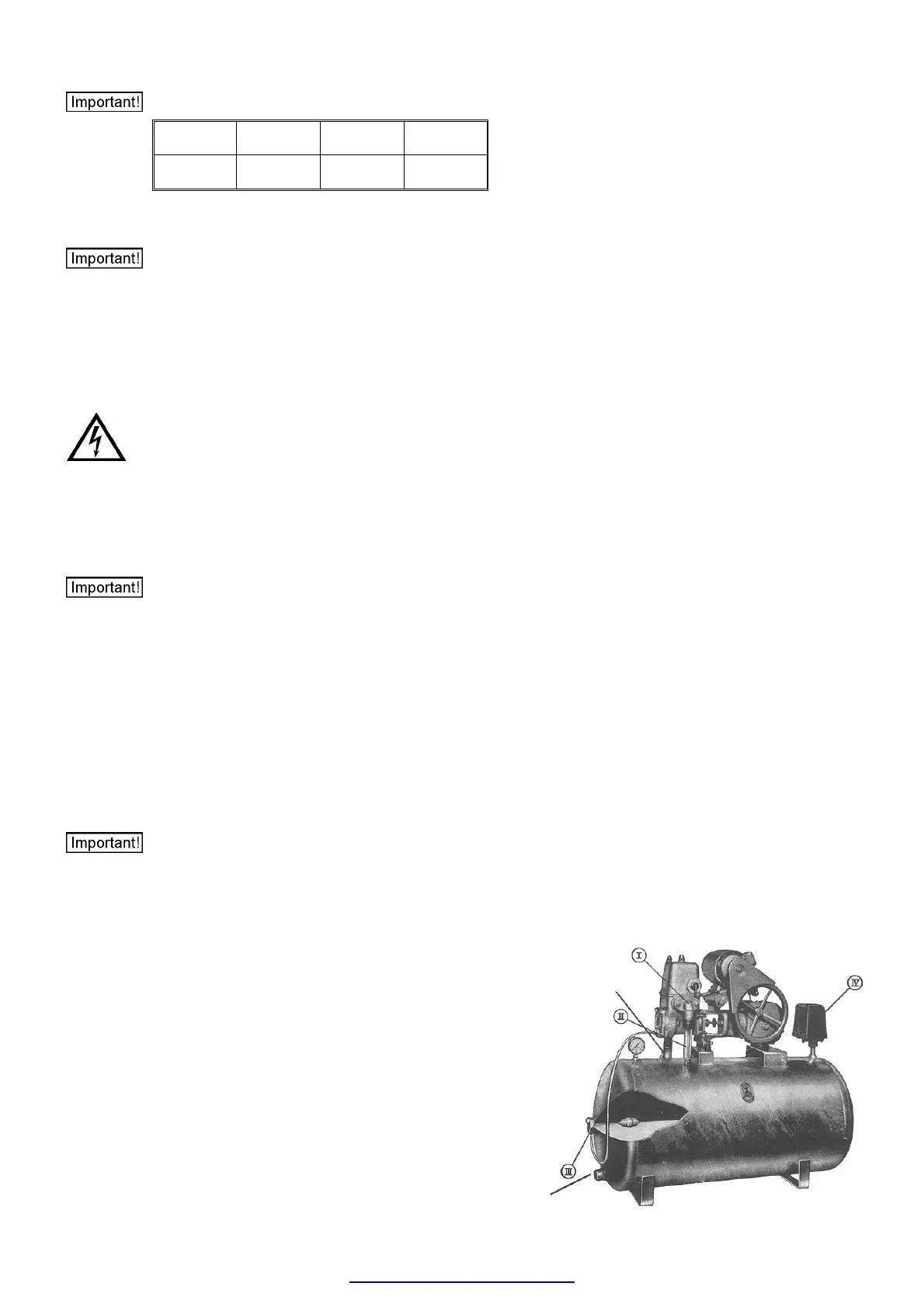
(clearly visible through transparent tube – fig. 111/II) and after water has come out of the tap. Depending
on the size of the tank, it takes between 5-15 minutes until the tank is full and the pressure switch
switches off at either 3.5 bar or 5.5 bar.
6.6 To Let Water Out
Turn tap on and let water out. Pressure drops eventually to 2 or 3 bar respectively and the pump switches
on again automatically. Only a few air bubbles should now be visible in the suction line, otherwise there is
reason to believe that the suction is not correctly sealed. Approximately 2000 litres of water per hour flow
out of an open G1/2 tap at 3 bar pressure.
6.7 On/Off Switching Pressure
(for 4 and 6 bar units)
The pump unit has a diaphragm safety valve which is adjusted to an activation pressure of either 4 or 6
bar. The pressure tank is also approved for max. pressure of 4 or 6 bar. The pressure switch must
therefore be adjusted to a maximum pressure of 3.5 bar / 5.5 bar otherwise it will activate the safety
valve. To readjust switch-on / switch-off pressure, see instructions on pressure-switch (Fig. 111/IV).
Switching Stages:
4 bar Pump Unit Switch-On Pressure 2 bar
Switch-Off Pressure 3,5 bar
6 bar Pump Unit Switch-On Pressure 3 bar
Switch-Off Pressure 5,5 bar
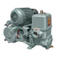
Fig. 111 Büffel Pump Unit
Suction Line
Dischar
e Line
 Loading...