D1835 0113S
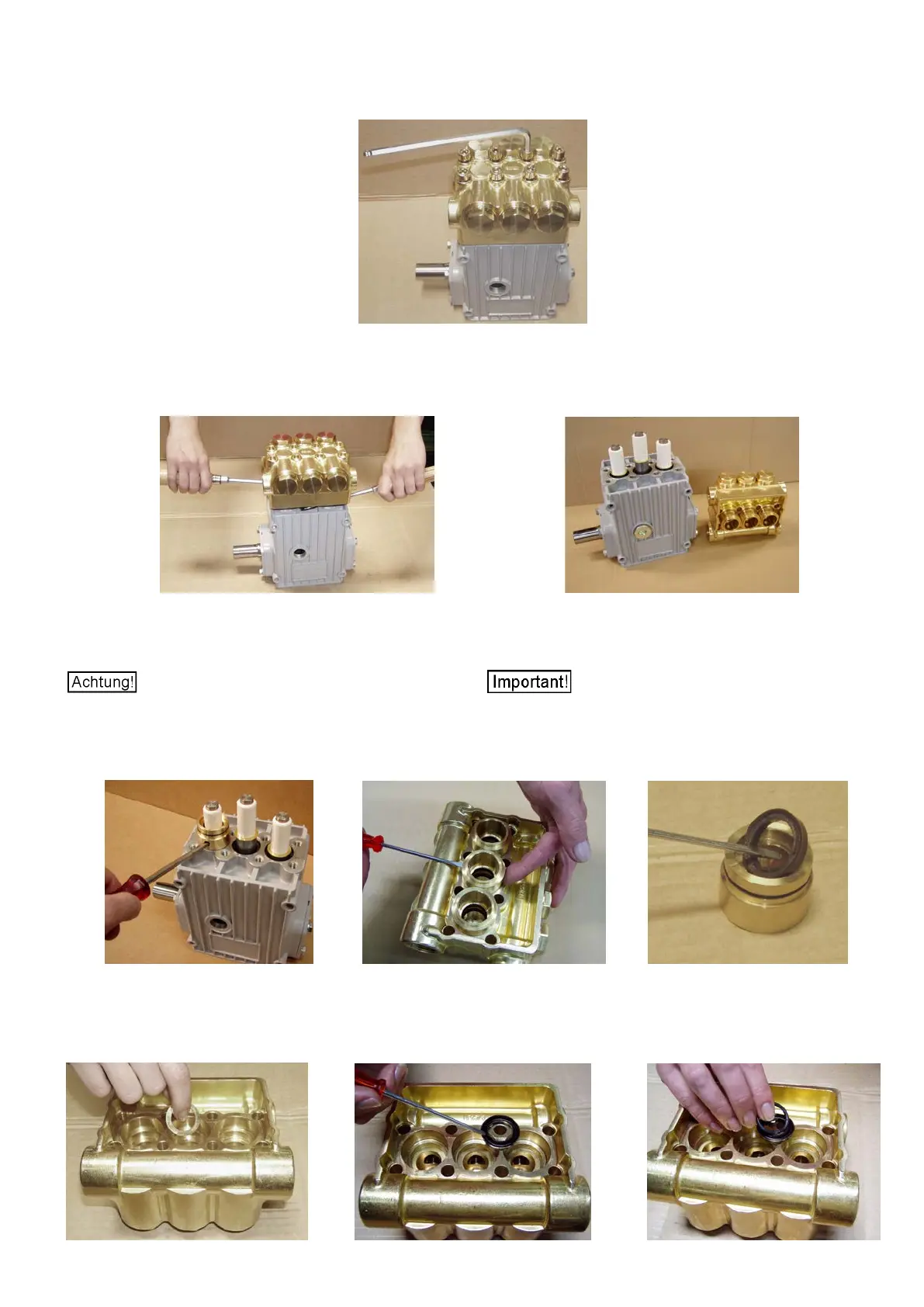
Bild / Photo 1
Ventilgehäuse mittels zwei Schra
u
bendrehern abheben (Bild 2), dabei
können die Dichtungsaufnahmen (20) im Antrieb oder
im Ventilgehäu
Lever off the valve casing using two screwdrivers (photo 2). The seal re-
tainers (20) will r
emain either in the drive or in the valve casing (photo 3).
Bild / Photo 2 Bild / Photo 3
aufnahmen vorsi
chtig durch Drehen und Anheben aus dem
Antriebsgehäuse (Bild 4) bzw. dem Pumpenkopf (Bild 5) entnehmen.
Take the seal sleeves out of the drive (photo 4) or pump head (photo 5)
by carefully turning and lifting them.
Plungeroberflächen nicht beschädigen.
Do not damage the plunger surfaces.
Verschlissene Dichtungen (23/23B) und Stützringe (24
–
nur NP25/41,
/50) vorsichtig aus den Dichtungsaufnahmen (20) entnehmen
(Bild 6).
Aus dem Ventilgehäuse Leckagerückfuhrringe (25), Stützringe (24),
Nutringe (23) bzw. Nutringdichtsätze (23) herausnehmen.
Carefully take worn seals (23/23B) (and support rings 24 if NP25/41 or
NP25/50 model) out of the seal r
etainers (20) (photo 4).
Take drip return rings (25), support rings (24), grooved rings (23) or al-
ternatively grooved seal ring packs (23) out of the valve casing.
Bild / Photo 4 Bild / Photo 5 Bild / Photo 6
Neue Dichtungen leicht mit Silikonfett schmieren. Distanzscheibe (23A)
in das Ventilgehäuse einlegen (nur NP25/30, /38) (Bild 7). Nutringe (23)
bzw
. Nutringdichtsätze (23B) mit der Profilrille (Bild 8 / 9) nach unten
in
das Ventilgehäuse (26) einsetzen.
Coat new seals lightly with silicon grease. Insert spacer disc (23A) into
the valve casing (if NP25/30 or NP25/38 model
–
photo 7). Insert
grooved rings (23) or alternatively grooved seal ring packs (23B) into
the valve casing (26) with the groove side down (photo 8 / 9).
Bild / Photo 7 Bild / Photo 8 Bild / Photo 9
8 x Innensechskantschrauben (34) am Ventilgehäuse (26) lösen (Bild 1).
Remove the 8 socket screws (34) (photo 1) on the valve casing (26).