D1835 0113S
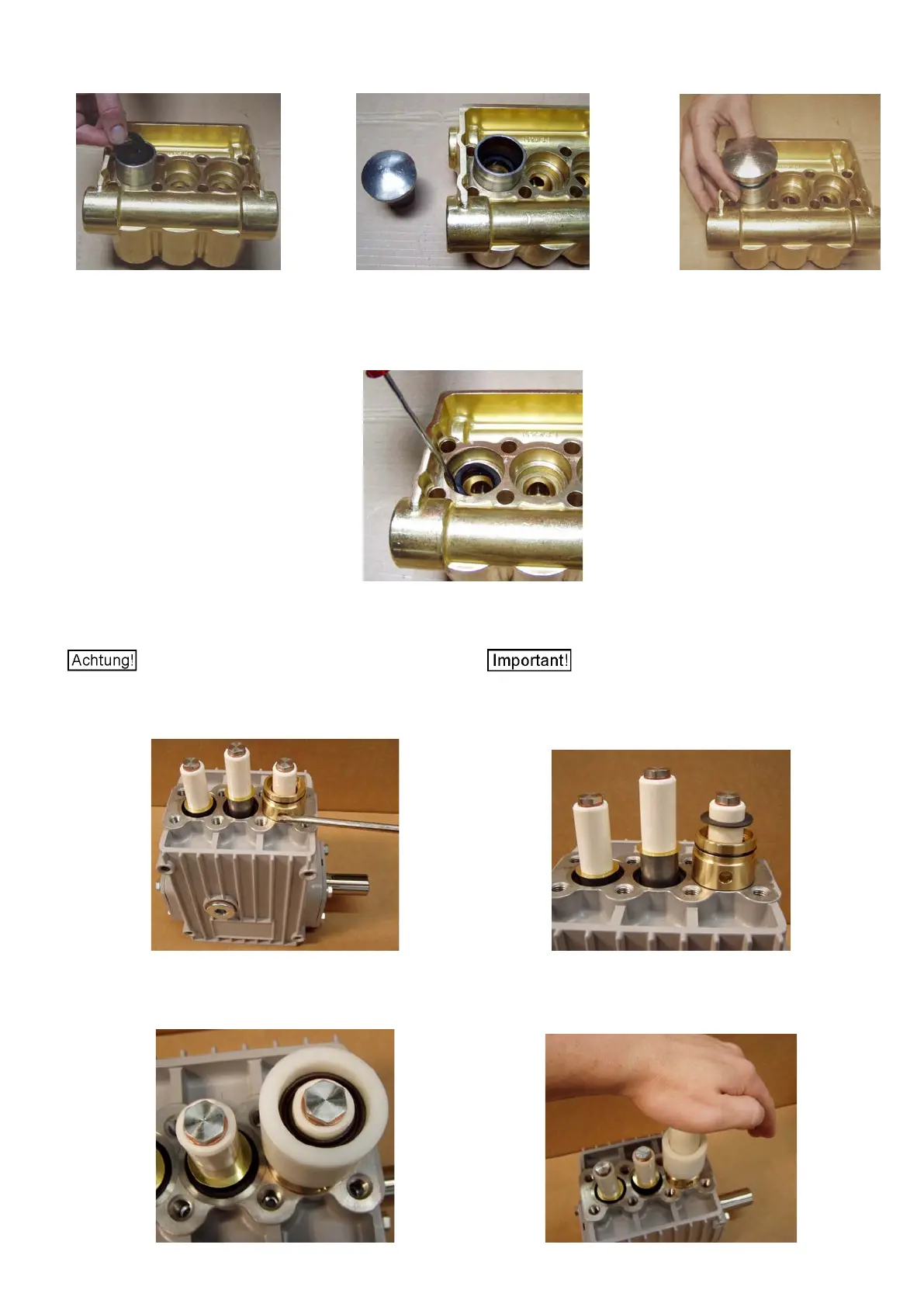
Hierzu am besten die Montagehilfen (Best.-Nr. 15.0933 / 15.0932 /
15.0931) benutzen (Bild 10-12).
It is best to use the mounting aids (code no. 15.0933 / 15.0932 /
15.0931) (photos 10-12).
Bild / Photo 10 Bild / Photo 11 Bild / Photo 12
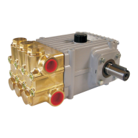
Falls diese Montagehilfen nicht vorhanden sind, die Dichtungen (23)
auf einer Se
ite in den Absatz des Ven
tilgehäuses (26) legen und dann
den restlichen Umfang durch seitliches Drücken mit der flachen Fläche
eines Schraubendrehers vorsichtig in den Absatz fädeln (Bild 13).
Should the mounting aids not be available, place the seal (23)
into the
valve casing (26) recess with one side up; then press the rest of the
seal into the recess little by little using the flat side of a screwdriver
(photo 13).
Bild / Photo 13
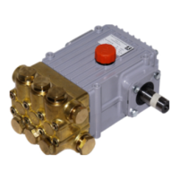
Dann die Dichtungsaufnahmen (20) auf den Antrieb stecken (Bild 14).
Mount the seal retainers (20) on to the drive (photo 14).
Die Leckagebohrungen der Dichtungsaufnahmen (20) mü
s-
sen nach unten zeigen damit das Leckwasser abtropfen kann (Bild 14).
The leakage bores of the seal retainers (20) must face
down so that drip water can exit (photo 14).
– nur bei NP25/41, /50) über die Plunger in die Dic
h-
tungsaufnahmen einlegen (Bild 15).
Place the support rings 24 (only on NP24/41 & NP25/50) into the seal
retainers by passing them past the plungers (photo 15).
Bild / Photo 14 Bild / Photo 15
Anschließend die Dichtung (23 / 23B) mit dem Profil nach oben mit den
Montagehilfen (Best.
-Nr. 15.0931 / 15.0932 / 15.0933) in die Dic
h-
tungsaufnahme drücken (Bild 16 / 17).
Finally push the seal (23 / 23B) with its groove pointing upwards into
the seal retainer using the mounting aids (code no. 15.0931 / 15.0932 /
15.0933) (photo 16 /17).
Bild / Photo 16 Bild / Photo 17