2 Setup, Connection, and Cabling
14 EPOCH 50 GNSS System User Guide
2.1 Parts of the receiver
All operating controls on the receiver are located on the front panel. Serial ports and
connectors are located on the bottom of the unit.
• The power button controls the receiver’s power on or off functions.
• LEDs show the status of power, satellite tracking, and radio reception. See also
LED display, page 25.
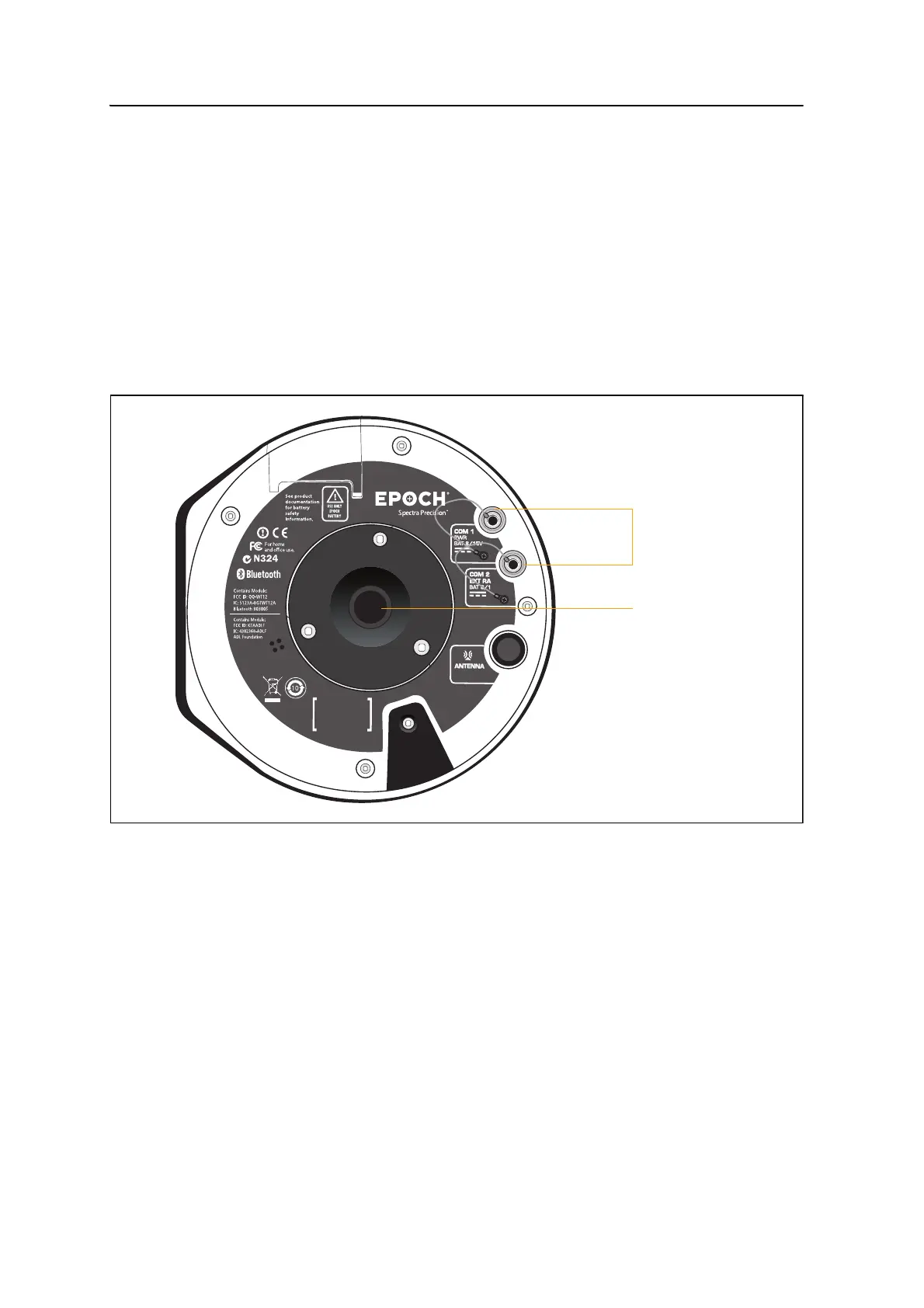
21.1 Ports and connectors
Figure 2.1 shows the two serial ports and the
5
/
8
-11 threaded insert.
Figure 2.1 Ports and connectors on the receiver
COM 1 and 2 are 7-pin 0-shell LEMO connectors that support serial communications
and external power input of 12 -20 VDC with no power output.
For more information, see Chapter 5, Default Settings and Chapter 6, Cables and
Connectors.
Serial ports
5
/
8
-11 threaded
insert
Note: Use the TNC
to connect the radio
antenna.
connector (not shown)