Spectracom Corporation PathAlign-R
2200 / 2240 / 2241 PathAlign-R Manual
data.
(2) The LED flashes briefly once every 4 seconds when the
GPS receiver i
s attempting to acquire satellites, indicating that
there are not enough satellites locked onto to provide a fix.
Date may be recorded without GPS lock but will lack position
information. If this LED is not illuminated in one of the
previously described wa
ys it indicates a failure of the GPS
receiver.
Note: The GPS antenna, the small plastic block located on the front panel of the
instrument, should face up to the sky for best signal acquisition and GPS lock.
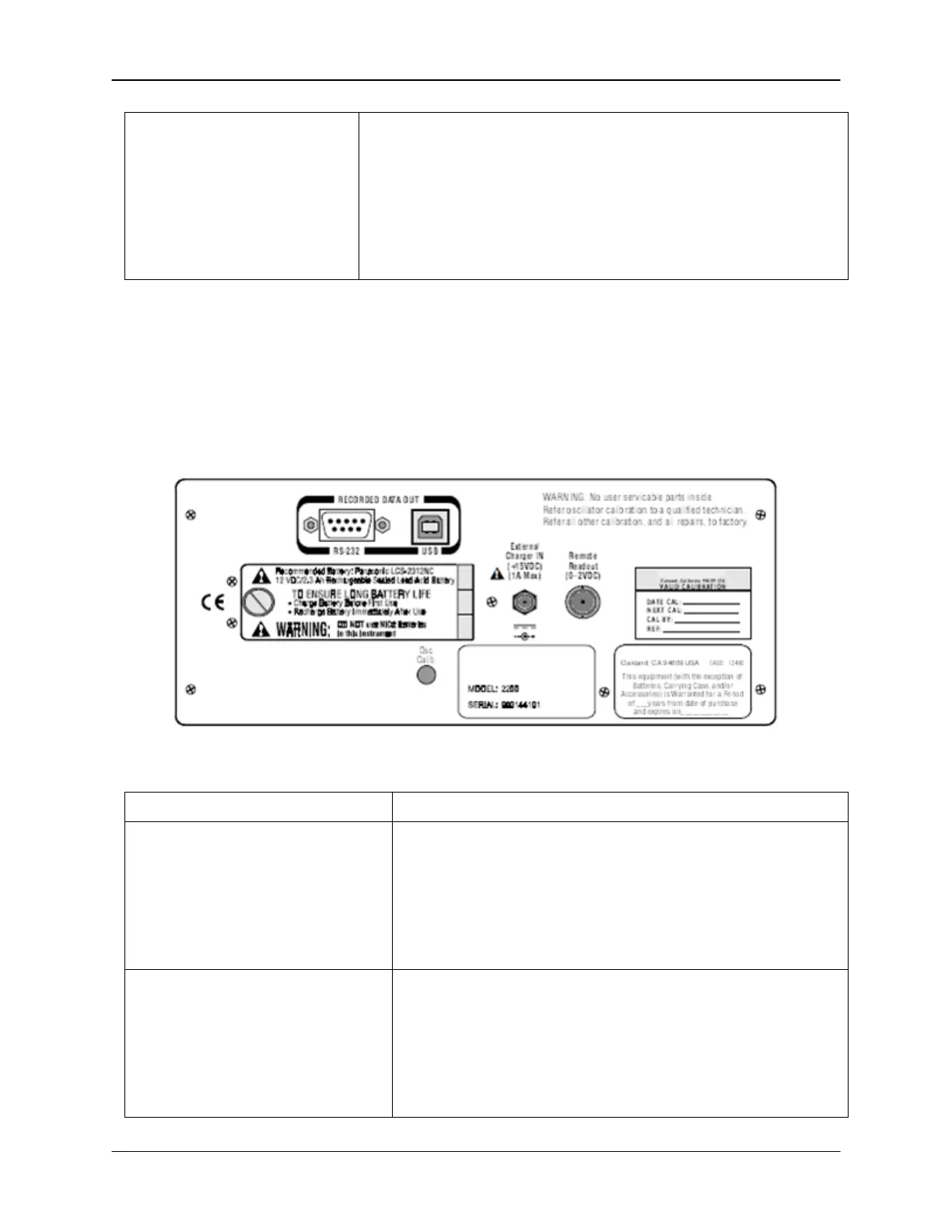
4.4 Rear Panel
The following figure depicts the rear panel connectors found on PathAlign-R with Record-R.
Standard 2241 rear panel connectors are described in section 3.
Figure 4-2. Model 2241 Rear Panel
DB-9 connector. The RS-232 RECORDED DATA OUT
connector provides a means for connecting a PC
computer to the instrument to download recorded data.
This connector conforms to the EIA RS-232-
Recommended Standard. The correct cable to use is a D-
sub 9-pin
male to female Extension Interface Cable (not a
Null Modem cable).
USB Series ’B’ connector for peripherals. The USB
RECORDED DATA OUT
connector provides a means for
connecting a PC computer to the
recorded dat
a. This USB Series ’B’ connector conforms to
all revisions of the Universal Serial Bus Specifications. The
USB data from the PathAlign-
R conforms to Revision 1.1
of the specification for Low-Speed peripherals, 1.5 Mb/s.