SpectraPure
®
Inc
. Fax 480.894.6109 Fax us toll-free 1.877.527.7873
sales@spectrapure.com www.spectrapure.com
5
SpectraPure
®
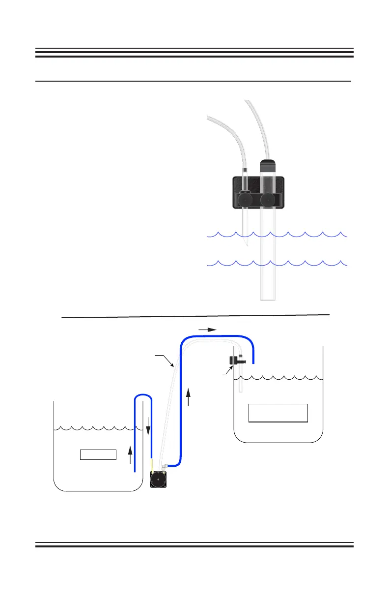
SETUP DIAGRAMS:
RESERVOIR
DISPLAY TANK
OR SUMP
MAGNETIC
PROBE
HOLDER
CLEAR AIR
LINE TUBING
(x2)
NORMAL WATER LEVEL
HIGH LIMIT WATER LEVEL
FRONT VIEW OF THE MAGNETIC
PROBE HOLDER
The high limit sensor will shut the
pump off if the water level reaches the
top of the bevel in the tube.
Position
the high limit sensor tube so any
abnormal rise in the sump will
deactivate the circuit and kill power
to the ATO control module. See
page 10 for instructions in setting the
high and low water levels.
The Sensor Tube should be
mounted in the display tank
or sump where the water level
changes due to evaporation.
Pump operation is dependent
upon the water level in relation
to the Sensor Tube.